


66
Chapter 3
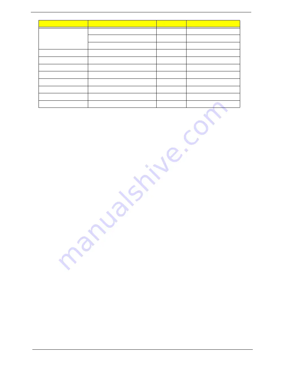
Upper Cover
M2.5*10
10
86.AD302.004
M2.5*5
6
86.AD302.003
M2.5*3
1
86.AD302.002
Finger Print Reader
M2*3
1
86.AD302.001
TouchPad Bracket
M2*3
2
86.AD302.001
eKey Board
M2.5*3
1
86.AD302.002
USB Board
M2.5*3
1
86.AD302.002
Modem Module
M2*3
2
86.AD302.001
BT Module
M2.5*3
1
86.AD302.002
Mainboard
M2.5*3
1
86.AD302.002
Thermal Module
M2.5*5*3.2
4
86.AD302.006
Step
Screw
Quantity
Part No.
Summary of Contents for Aspire 4935 Series
Page 6: ...VI ...
Page 10: ...X Table of Contents ...
Page 60: ...50 Chapter 2 ...
Page 68: ...58 Chapter 3 7 Carefully open the HDD Cover ...
Page 95: ...Chapter 3 85 5 Remove the TouchPad Bracket from the Upper Base ...
Page 100: ...90 Chapter 3 5 Lift the USB Board clear of the casing ...
Page 104: ...94 Chapter 3 7 Lift the mainboard right side first to remove from the base ...
Page 112: ...102 Chapter 3 4 Lift the bezel away from the panel ...
Page 115: ...Chapter 3 105 4 Lift the LCD Panel out of the casing as shown ...
Page 122: ...112 Chapter 3 13 Ensure that the securing pin is properly located ...
Page 130: ...120 Chapter 3 7 Insert the cable through the casing to the top side as shown ...
Page 143: ...Chapter 3 133 13 Replace the two securing screws ...
Page 148: ...138 Chapter 3 4 Turn the computer over and replace the six securing screws as shown ...
Page 154: ...144 Chapter 3 ...
Page 193: ...Chapter 6 183 ...
Page 232: ...Appendix A 222 ...
Page 240: ...230 Appendix C ...