


Chapter 1
13
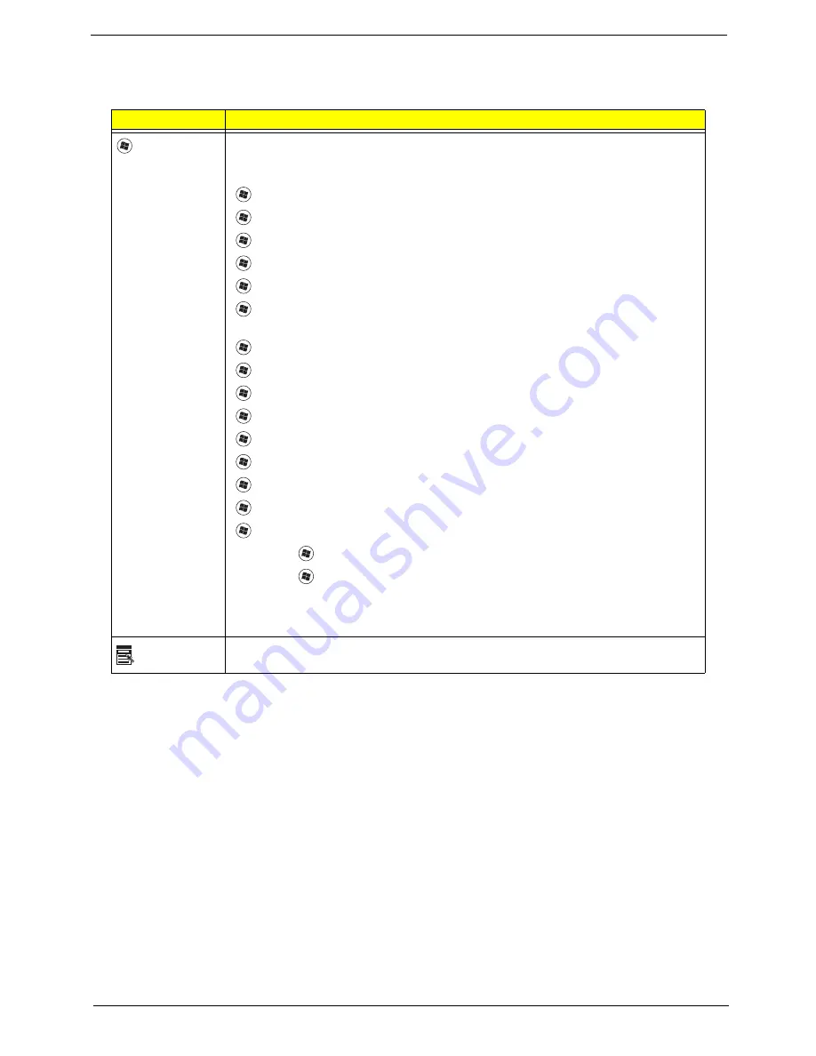
Windows Keys
The keyboard has two keys that perform Windows-specific functions.
Key
Description
Windows key
Pressed alone, this key has the same effect as clicking on the Windows Start button;
it launches the Start menu. It can also be used with other keys to provide a variety of
functions:
<
>
:
Open or close the Start menu
<
>
+ <D>:
Display the desktop
<
>
+ <E>:
Open Windows Explore
<
>
+
<F>:
Search for a file or folder
<
>
+
<G>:
Cycle through Sidebar gadgets
<
>
+
<L>:
Lock your computer (if you are connected to a network domain), or
switch users (if you're not connected to a network domain)
<
>
+
<M>:
Minimizes all windows
<
>
+ <R>:
Open the Run dialog box
<
>
+
<T>:
Cycle through programs on the taskbar
<
>
+ <U>:
Open Ease of Access Center
<
>
+
<X>:
Open Windows Mobility Center
<
>
+
<BREAK>: Display
the System Properties dialog box
<
>
+ <SHIFT+M>:
Restore minimized windows to the desktop
<
>
+ <TAB>:
Cycle through programs on the taskbar by using Windows Flip 3-D
<
>
+ <SPACEBAR>:
Bring all gadgets to the front and select Windows Sidebar
<CTRL> +
<
>
+ <F>:
Search for computers (if you are on a network)
<CTRL> +
<
>
+ <TAB>:
Use the arrow keys to cycle through programs on the
taskbar by using Windows Flip 3-D
Note:
Depending on your edition of Windows Vista, some shortcuts may not function
as described.
Application
key
This key has the same effect as clicking the right mouse button; it opens the
application's context menu.
Summary of Contents for Aspire 4935 Series
Page 6: ...VI ...
Page 10: ...X Table of Contents ...
Page 60: ...50 Chapter 2 ...
Page 68: ...58 Chapter 3 7 Carefully open the HDD Cover ...
Page 95: ...Chapter 3 85 5 Remove the TouchPad Bracket from the Upper Base ...
Page 100: ...90 Chapter 3 5 Lift the USB Board clear of the casing ...
Page 104: ...94 Chapter 3 7 Lift the mainboard right side first to remove from the base ...
Page 112: ...102 Chapter 3 4 Lift the bezel away from the panel ...
Page 115: ...Chapter 3 105 4 Lift the LCD Panel out of the casing as shown ...
Page 122: ...112 Chapter 3 13 Ensure that the securing pin is properly located ...
Page 130: ...120 Chapter 3 7 Insert the cable through the casing to the top side as shown ...
Page 143: ...Chapter 3 133 13 Replace the two securing screws ...
Page 148: ...138 Chapter 3 4 Turn the computer over and replace the six securing screws as shown ...
Page 154: ...144 Chapter 3 ...
Page 193: ...Chapter 6 183 ...
Page 232: ...Appendix A 222 ...
Page 240: ...230 Appendix C ...