


38
Chapter 2
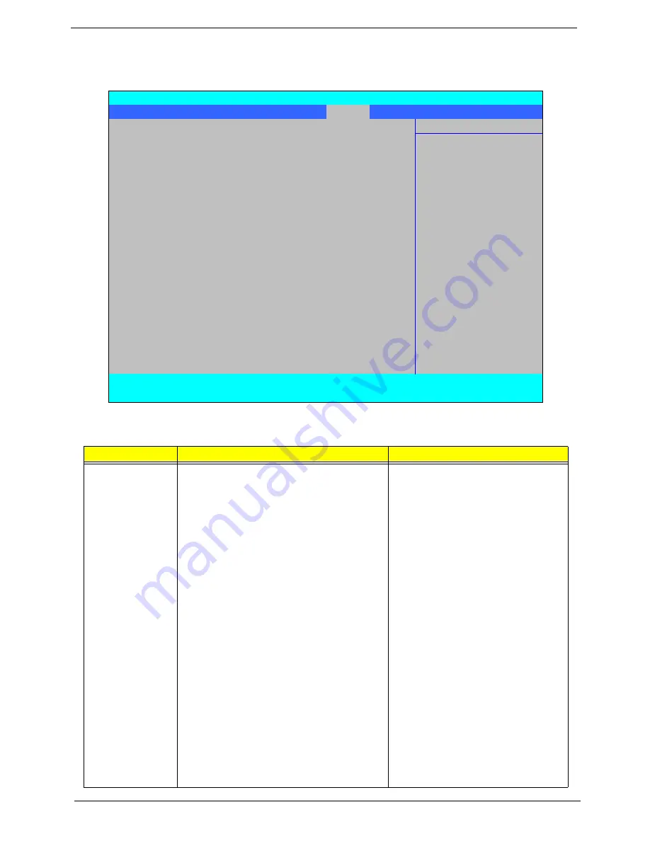
Power
The Power screen allows the user to configure CPU and power management options.
The table below describes the items, menus, and submenus in this screen. Settings in
boldface
are the default
and suggested parameter settings.
Parameter
Description
Submenu Items
Advanced CPU
Control
Enter the Advanced CPU Control menu.
•
P-States (IST)
•
Boot performance mode
•
Thermal Mode
•
CMP Support
•
Use XD capability
•
VT Support
•
SMRR Support
•
C-States
•
Enhanced C-States
•
C-State Pop Up Mode
•
C-State Pop Down Mode
•
C4 Exit Timing Mode
•
DeepC4
•
Hard C4E
•
Enable C6
•
EMTTM
•
Bi-directional PROCHOT#
•
Dynamic FSB Switching
•
Turbo Mode
•
ACPI 3.0 T-States
•
DTS
•
DTS Calibration
•
Thermal Trip Points Setting (Fan
On Temp., Throttle On Temp.)
InsydeH20 Setup Utility
Rev 3.5
Information Main Advanced
Security
Power
Boot
Exit
Item Specific Help
X
Advanced CPU Control
X
Platform Power Management
These items control
X
Break Event
various CPU paramaters.
ACPI S3:
[Enabled]
Wake on PME
[Enabled]
Wake on Modem Ring
[Enabled]
Quickly S4 Resume
[Disabled]
Auto Wake on S5
[Disabled]
F1
Help
↑↓
Select Item
F5/F6
Change Values
F9
Setup Default
ESC
Exit
←→
Select Menu
Enter
Select
X
Submenu
F10
Save and Exit
Summary of Contents for Aspire 4935 Series
Page 6: ...VI ...
Page 10: ...X Table of Contents ...
Page 60: ...50 Chapter 2 ...
Page 68: ...58 Chapter 3 7 Carefully open the HDD Cover ...
Page 95: ...Chapter 3 85 5 Remove the TouchPad Bracket from the Upper Base ...
Page 100: ...90 Chapter 3 5 Lift the USB Board clear of the casing ...
Page 104: ...94 Chapter 3 7 Lift the mainboard right side first to remove from the base ...
Page 112: ...102 Chapter 3 4 Lift the bezel away from the panel ...
Page 115: ...Chapter 3 105 4 Lift the LCD Panel out of the casing as shown ...
Page 122: ...112 Chapter 3 13 Ensure that the securing pin is properly located ...
Page 130: ...120 Chapter 3 7 Insert the cable through the casing to the top side as shown ...
Page 143: ...Chapter 3 133 13 Replace the two securing screws ...
Page 148: ...138 Chapter 3 4 Turn the computer over and replace the six securing screws as shown ...
Page 154: ...144 Chapter 3 ...
Page 193: ...Chapter 6 183 ...
Page 232: ...Appendix A 222 ...
Page 240: ...230 Appendix C ...