


32
Chapter 2
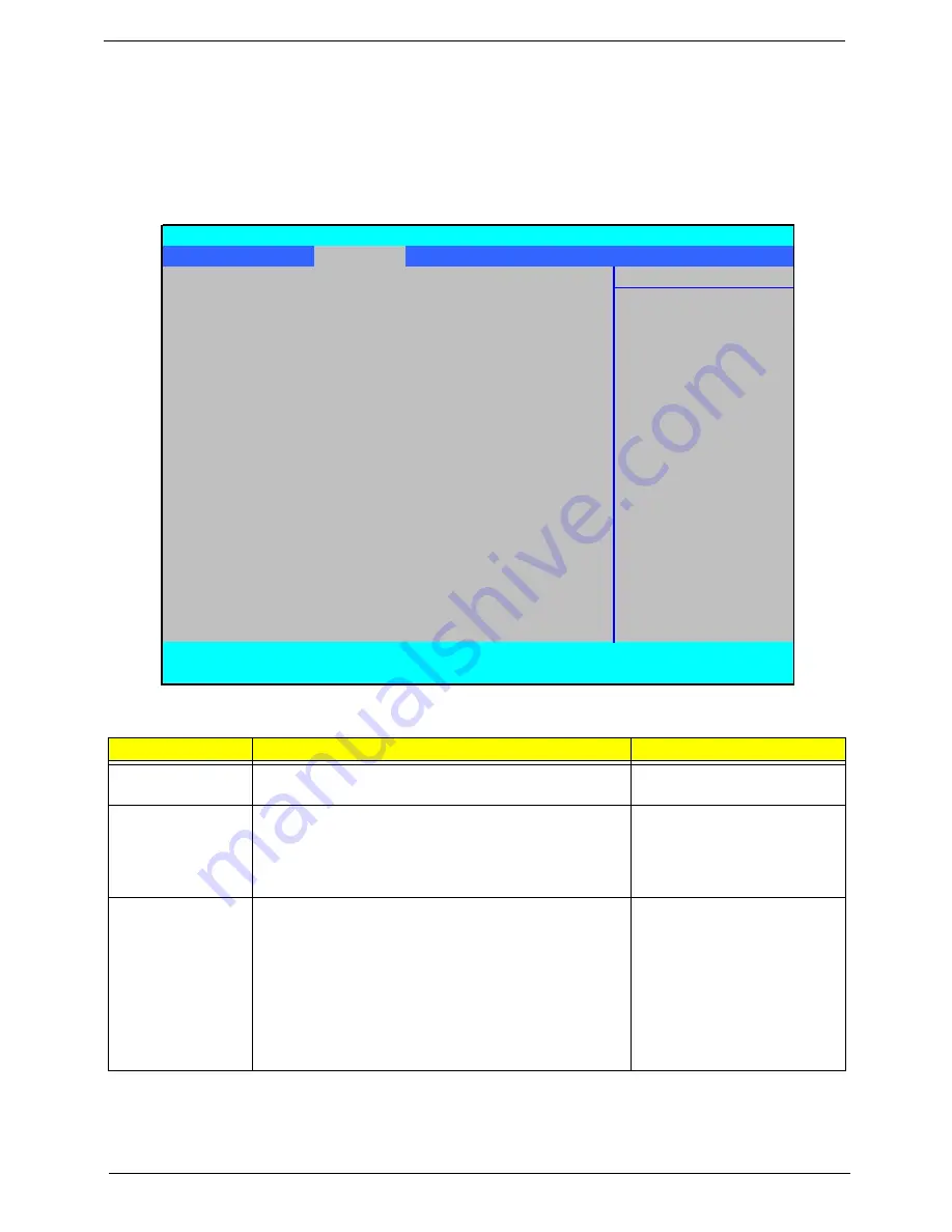
Advanced
The Advanced screen allows the user to configure the various advanced BIOS options.
IMPORTANT:
Making incorrect settings to items on these pages may cause the system to malfunction. Unless
you have experience adjusting these items, we recommend that you leave these settings at the default values.
If making settings to items on these pages causes your system to malfunction or prevents the system from
booting, open BIOS and choose Load Optimal Defaults in the Exit menu to boot up normally.
The table below describes the parameters in this screen. Settings in
boldface
are the default and suggested
parameter settings.
Parameter
Description
Submenu Items
Boot
Configuration
Enter the Boot Configuration menu.
•
Numlock
Peripheral
Configuration
Enter the Peripheral Configuration menu.
•
Serial Port A
•
Infrared Port
•
Azalia
•
Lan
IDE Configuration
Enter the IDE Configuration menu.
•
IDE Controller
•
HDC Configure as
•
AHCI Option ROM
Support
•
SATA Port 0, 1, 4, and 5
Hotplug
X
Channel 1 to 4 Master
X
Channel 1 to 4 Slave
InsydeH20 Setup Utility
Rev 3.5
Information Main
Advanced
Security
Power
Boot
Exit
Item Specific Help
X
Boot Configuration
X
Peripheral Configuration
Configures Boot
X
IDE Configuration
Settings.
X
Video Configuration
X
USB Configuration
X
Chipset Configuration
X
ACPI Table/Features Control
Express Card
[Disabled]
X
PCI Express Root Port 1
X
PCI Express Root Port 2
X
PCI Express Root Port 3
X
PCI Express Root Port 4
X
PCI Express Root Port 5
X
PCI Express Root Port 6
X
ASF Configuration
F1
Help
↑↓
Select Item
F5/F6
Change Values
F9
Setup Default
ESC
Exit
←→
Select Menu
Enter
Select
X
Submenu
F10
Save and Exit
Summary of Contents for Aspire 4935 Series
Page 6: ...VI ...
Page 10: ...X Table of Contents ...
Page 60: ...50 Chapter 2 ...
Page 68: ...58 Chapter 3 7 Carefully open the HDD Cover ...
Page 95: ...Chapter 3 85 5 Remove the TouchPad Bracket from the Upper Base ...
Page 100: ...90 Chapter 3 5 Lift the USB Board clear of the casing ...
Page 104: ...94 Chapter 3 7 Lift the mainboard right side first to remove from the base ...
Page 112: ...102 Chapter 3 4 Lift the bezel away from the panel ...
Page 115: ...Chapter 3 105 4 Lift the LCD Panel out of the casing as shown ...
Page 122: ...112 Chapter 3 13 Ensure that the securing pin is properly located ...
Page 130: ...120 Chapter 3 7 Insert the cable through the casing to the top side as shown ...
Page 143: ...Chapter 3 133 13 Replace the two securing screws ...
Page 148: ...138 Chapter 3 4 Turn the computer over and replace the six securing screws as shown ...
Page 154: ...144 Chapter 3 ...
Page 193: ...Chapter 6 183 ...
Page 232: ...Appendix A 222 ...
Page 240: ...230 Appendix C ...