104
Chapter 3
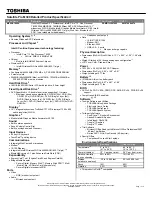
Removing the LCD Panel
1.
See “Removing the Camera Module” on page 103.
2.
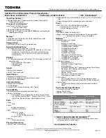
Remove the two securing screws from the LCD hinges and the single LCD grounding screw.
3.
Remove the Camera cable bundle from the top of the casing as shown.
Step
Size
Quantity
Screw Type
LCD Panel
(red callout)
M2.5*5
2
LCD Panel
(green callout)
M2.5*3
1
Summary of Contents for Aspire 4935 Series
Page 6: ...VI ...
Page 10: ...X Table of Contents ...
Page 60: ...50 Chapter 2 ...
Page 68: ...58 Chapter 3 7 Carefully open the HDD Cover ...
Page 95: ...Chapter 3 85 5 Remove the TouchPad Bracket from the Upper Base ...
Page 100: ...90 Chapter 3 5 Lift the USB Board clear of the casing ...
Page 104: ...94 Chapter 3 7 Lift the mainboard right side first to remove from the base ...
Page 112: ...102 Chapter 3 4 Lift the bezel away from the panel ...
Page 115: ...Chapter 3 105 4 Lift the LCD Panel out of the casing as shown ...
Page 122: ...112 Chapter 3 13 Ensure that the securing pin is properly located ...
Page 130: ...120 Chapter 3 7 Insert the cable through the casing to the top side as shown ...
Page 143: ...Chapter 3 133 13 Replace the two securing screws ...
Page 148: ...138 Chapter 3 4 Turn the computer over and replace the six securing screws as shown ...
Page 154: ...144 Chapter 3 ...
Page 193: ...Chapter 6 183 ...
Page 232: ...Appendix A 222 ...
Page 240: ...230 Appendix C ...