


4
Chapter 1
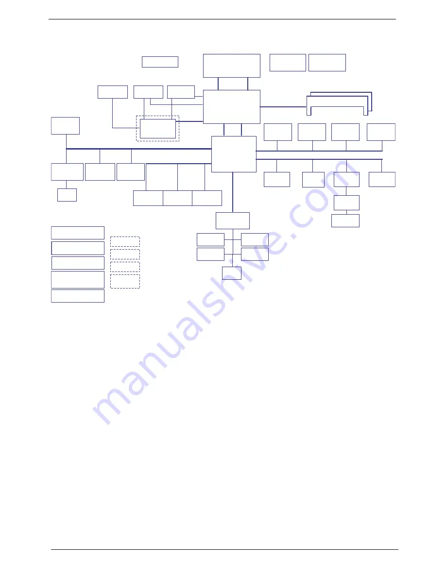
System Block Diagram
Power On/Off CKT.
Touch Pad
CRT Conn.
LPC BUS
uFCBGA-1329
H_A#(3..35)
H_D#(0..63)
MDC 1.5
Conn
Int.KBD
PCI-Express
BANK 0, 1, 2, 3
USB conn x3
667/800/1066MHz
ALC888S-VC
DMI
DC/DC Interface CKT.
Intel Penryn Processor
3.3V 48MH
z
FSB
Clock Generator
ICS9LPRS387
EC I/O Buffer
Fan Control
Power Circuit DC/DC
uPGA-478 Package
200pin DDRII-SO-DIMM X2
Intel Cantiga
BIOS
1.8V DDRII 533/667
page 4,5,6
HDA Codec
Memory BUS(DDRII)
BGA-676
HD Audio
Intel ICH9-M
Thermal Sensor
ENE KB926
Audio AMP
LCD Conn.
VGA
Bluetooth
Conn
3.3V 24.576MH
z/48Mhz
Phone Jack x3
Dual Channel
USB/B Conn.
HDMI Conn.
EMC 1402
FUN Conn.
CIR
USB port 1
LVDS
LVDS
TMDS
C-Link
MINI Card x2
CMOS
Camera
WLAN, Robson2
PCI-Express
USB port 0, 2, 5
USB
(Socket P)
E_KEY/B Conn.
16X
S-ATA
GMCH HDA
Finger Print
AES1610
RTC CKT.
Card Reader
JMB385
Media/B Conn.
LS-4494P
VGA HDA
LS-4498P
LS-4493P
LS-4492P
LS-4495P
New Card
Socket
LAN(GbE)
ATHEROS AR8121
RJ45
port 2
ESATA
Conn.
CDROM
Conn.
port 1
port 0
SATA HDD
Conn.
POWER SW
Summary of Contents for Aspire 4935 Series
Page 6: ...VI ...
Page 10: ...X Table of Contents ...
Page 60: ...50 Chapter 2 ...
Page 68: ...58 Chapter 3 7 Carefully open the HDD Cover ...
Page 95: ...Chapter 3 85 5 Remove the TouchPad Bracket from the Upper Base ...
Page 100: ...90 Chapter 3 5 Lift the USB Board clear of the casing ...
Page 104: ...94 Chapter 3 7 Lift the mainboard right side first to remove from the base ...
Page 112: ...102 Chapter 3 4 Lift the bezel away from the panel ...
Page 115: ...Chapter 3 105 4 Lift the LCD Panel out of the casing as shown ...
Page 122: ...112 Chapter 3 13 Ensure that the securing pin is properly located ...
Page 130: ...120 Chapter 3 7 Insert the cable through the casing to the top side as shown ...
Page 143: ...Chapter 3 133 13 Replace the two securing screws ...
Page 148: ...138 Chapter 3 4 Turn the computer over and replace the six securing screws as shown ...
Page 154: ...144 Chapter 3 ...
Page 193: ...Chapter 6 183 ...
Page 232: ...Appendix A 222 ...
Page 240: ...230 Appendix C ...