Chapter
4 Configuration
Installation and Operation Manual
4-48
Configuring for Operation
ACE-3105, ACE-3205 Ver. 5.2
ACE-3205 – RAD Data Communications
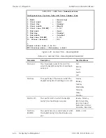
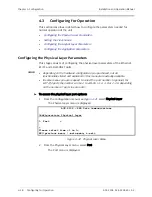
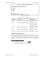
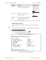
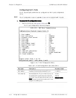
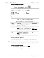
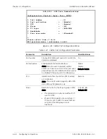
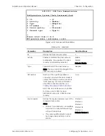
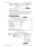
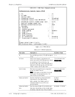
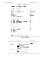
Configuration> Physical layer> Port> SHDSL
1. Port number ... (1)
2. Port activation > (Enable)
3. STU > (Remote)
4. Wires > (2W)
5. TC layer > (ATM-IMA)
6. Handshake >
7. Four wire mode > (Standard)
>
Please select item <1 to 8>
ESC-previous menu; !-main menu; &-exit
Figure
4-38. SHDSL Port Configuration Menu
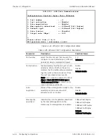
Table
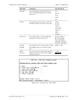
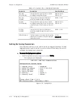
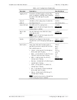
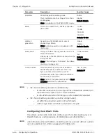
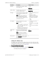
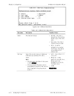
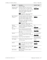
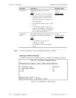
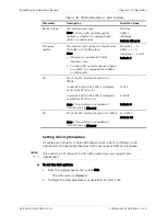
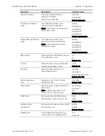
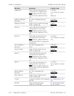
4-32. SHDSL Port Configuration Parameters
Parameter Description
Possible
Values
Port number
The specific SHDSL port number for which the
details are displayed
1–4
Port activation
Enable/disable the SHDSL interface.
Note: When the port is disabled, neither
events nor traps are sent from this port upon
physical layer events. SHDSL interfaces cannot
be disabled if they are part of an IMA group.
Enable
Disable
Default: Enable
STU
Indicates whether the unit is a CPE (Remote)
or CO (Central)
Note: The current version supports ACE-3105,
ACE-3205 as CPE (Remote) only.
Remote
Wires
Number of wires for the M-pair group or IMA.
Note:
•
This parameter can only be modified if TC
is set to ATM.
•
M-pair (ATM) supports only one group. If
TC Layer is set to ATM, the wires that are
not part of the IMA group are not
functional.
2W, 4W, 8W
Default: 2W

