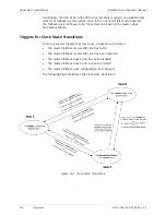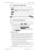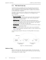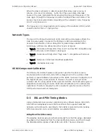
Appendix
C ATM OAM Functionality
Installation and Operation Manual
C-6
OAM Modes of Operation over ATM
ACE-3105, ACE-3205 Ver. 5.2
•
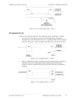
When a failure is detected on the physical port, AIS state is declared. F4
end-to-end AIS cells are generated towards the forward direction, while F4
segment RDI cells are generated towards the backward direction.
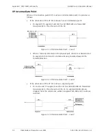
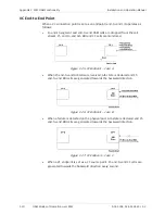
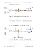
Figure
C-13. VP Segment Point – Case C
•
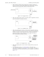
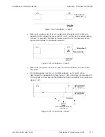
When a VP segment point is set as a CC source point, F4 segment CC cells are
generated towards the backward direction.
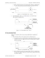
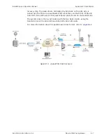
Figure
C-14. VP Segment Point – Case D
•
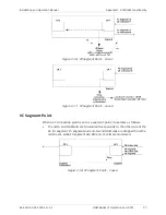
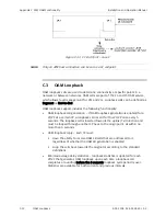
When a VP segment point is set as a CC sink point, F4 segment CC cells are
expected to be received every second. If no CC cell has been received during
the last 3.5 seconds, an AIS state is declared, F4 end-to-end AIS cells are
generated towards the forward direction and F4 segment RDI cells are
generated towards the backward direction.
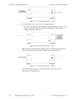
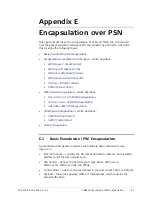
Figure
C-15. VP Segment Point – Case E
•
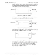
When a VP segment point is set as CC both, it behaves both as source and
sink point.
•
For OAM loopback cells (see
), an ID match check
determines the loopback state (see
), and delays are calculated if
the loopback cell has been authenticated and returned within 5 seconds (see
):


