Chapter
6 Monitoring and Diagnostics
Installation and Operation Manual
6-88
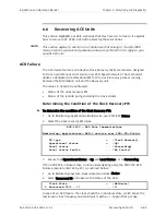
Recovering ACE Units
ACE-3105, ACE-3205 Ver. 5.2
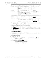
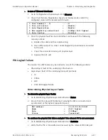
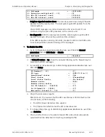
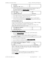
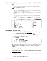
Rx Correct frames ... (175)
Rx Correct bytes ... (12220)
Tx Correct frames ... (175)
Tx Correct bytes ... (12220)
Rx FCS errors ... (0)
Rx Congestion dropped ... (0)
Rx Alignment errors ... (0)
Single collisions ... (0)
Multiple collisions ... (0)
Deferred transmit ... (0)
Late collisions .. (0)
3.
Ensure that there are no errors, such as FCS, Rx alignment and collisions.
Errors indicate a problem on the physical layer (FCS errors) or duplex issues
working opposite the access/switch router.
Massive FCS/collision errors will dramatically affect the ability of the PW to create
a valid connection.
To determine logical layer faults of the underlying infrastructure, follow the
instructions in the next section.
Logical Layer Faults
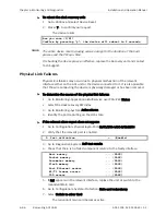
This section explains on identifying errors on IP (ARP), PPPoE, LDP and VCCV-BF.
IP (ARP)
³
To determine logical layer faults on IP (ARP):
1.
Go to Monitoring>Applications>Router>ARP table.
2.
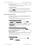
Verify that the remote device (Layer 2 networks) or default gateway MAC
address was learnt by the local ACE unit.
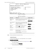
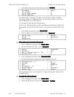
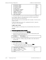
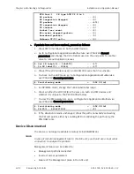
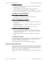
IP address MAC address
192.168.100.1 00-20-D2-2A-60-55
3.
If this is not the case, attempt to ping the address in its subnet from the
local ACE unit:
³
To ping the remote device:
1.
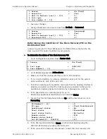
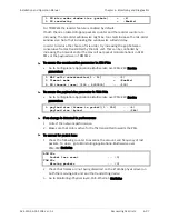
Go to Diagnostics>Applications>IP>Ping.
2.
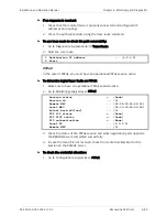
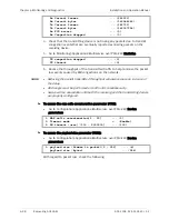
Specify the remote device’s IP address and then select Start.
The local ACE unit starts pinging the remote device.
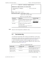
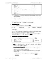
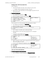
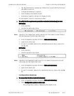
1. Destination IP address ... (0.0.0.0)
2. Infinite number of packets > (No)
3. Number of Packets[1 - 10000] ... (1)
4. Payload Size[32 - 1450] ... (32)
5. Start

