ABIMIG
®
SpinArc
®
4 Scope of delivery
EN - 5
3.2 Abbreviations
3.3 Signs and symbols used
The following signs and symbols are used in the operating instructions:
4 Scope of delivery
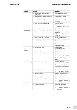
Maximum current intensity
350 A at 100% duty cycle with M21 gas
Rotation diameter
1-8 mm at the contact tip
Direction of rotation
Clockwise and counter-clockwise
Rotation start delay
0-5 sec.
Rotational speed
200-5,500 s
-1
Wire diameter
0.90-1.6 mm
Welding processes
MSG (gas shielded metal arc welding)
Control device input power
110-240 V AC, 50/60 Hz
Hose length
Available in 3 m, 4 m and 5 m
Conformity
RoHS
IP 51, control device
IEC/EN 60974-7
Low-Voltage Directive 2014/35/EU
Tab. 3
General torch data (EN 60974-7)
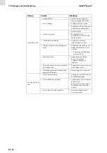
AC
Alternating current
TC
Trigger control cable
Tab. 4
Abbreviations
Symbol
Description
•
Bullet symbol for instructions and lists
Cross-reference symbol refers to detailed, supplementary or further information
1
Step(s) described in the text to be carried out in succession
• Cable assembly
• Torch body
• Control device
• Control lead
• Trigger control cable
• Flexure mounting tool
• Replacement flexures
• Replacement o-rings
The following components are required to ensure full functionality of the
ABIMIG
®
SpinArc
®
welding
torch system:
• Central connector (depends on wire feed)
• PP-EURO contact tips
• Nozzles
• Liner
Tab. 5
Scope of delivery

