9.2
Trip Points
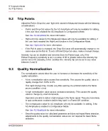
Adjust the Pull-In, Drop-Out, and High-Limit values for Measured-Values with the following
considerations:
–
Pull-In and Drop-Out values for the AC-Amplitude will only be available for editing,
if the user have enabled the AC-Amplitude in Configuration-Mode.
See
for more information.
–
High-Limit trip values for the Measured-Values will only be available for editing, if
the user have enabled the High-Limit function in the Configuration-Mode.
See
for more information.
–
If the Pull-In value is changed, the Drop-Out value will automatically change to the
same value as the Pull-In. To set a different Drop-Out value, make a manual change.
Intensity trip can be disabled and removed from the Flame-Logic only, if the
Flicker-Frequency sensitivity is set to a value of 65 or greater before the intensity trip
can be set to 0% (actually, in this condition the intensity trip can be set to any value
between 4 and 0).
9.3
Quality Normalization
The normalization values allow the user to increase or decrease the sensitivity of the
quality calculation.
–
A low normalization value causes less sensitivity. This causes the quality value to
rapidly change from 100% to 0%.
This rapid change may provide very little warning of a problem before the flame
proven condition is lost.
–
A high normalization value causes increased sensitivity. This causes the quality
value to change by small increments.
Operators are able to detect small changes in the flame signal. They are more likely
to spot combustion problems before they lead to a Flame-Off condition.
–
The normalization value for AC-Amplitude will only be available for editing, if the
AC-Amplitude is enabled in Configuration-Mode.
See
for more information.
–
Since the quality value is a calculated parameter and does not impact flame detection,
adjustments to the quality normalization values are not required for basic flame
detection.
8VZZ005286 B
74
9 Program-Mode
9.2 Trip Points
Summary of Contents for Uvisor SF910i
Page 2: ......
Page 6: ......
Page 20: ...8VZZ005286 B 20...
Page 30: ...8VZZ005286 B 30...
Page 68: ...8VZZ005286 B 68...
Page 78: ...8VZZ005286 B 78...
Page 90: ...8VZZ005286 B 90...
Page 92: ...8VZZ005286 B 92...
Page 98: ...8VZZ005286 B 98...
Page 108: ...8VZZ005286 B 108...
Page 114: ...8VZZ005286 B 114...
Page 118: ...8VZZ005286 B 118...
Page 126: ...8VZZ005286 B 126...
Page 128: ...8VZZ005286 B 128...
Page 130: ...8VZZ005286 B 130...
Page 150: ...8VZZ005286 B 150...
Page 151: ...Appendix E Drawings 8VZZ005286 B 151 E Drawings...
Page 152: ...Figure E 1 Enclosure Quick Release Connector and Version LOS 8VZZ005286 B 152 E Drawings...
Page 153: ...Figure E 2 Enclosure NPT Cable Inlet and Version LOS 8VZZ005286 B 153 E Drawings...
Page 154: ...Figure E 3 Enclosure Quick Release Connector and Version FOC 8VZZ005286 B 154 E Drawings...
Page 155: ...Figure E 4 Enclosure NPT Cable Inlet and Version FOC 8VZZ005286 B 155 E Drawings...
Page 156: ...Figure E 5 FOC Flexible Assembly 8VZZ005286 B 156 E Drawings...
Page 157: ...Figure E 6 FOC Rigid Assembly 8VZZ005286 B 157 E Drawings...
Page 160: ...Figure E 9 Bailey Flame ON Standard Replacement 8VZZ005286 B 160 E Drawings...
Page 161: ...Figure E 10 Typical Bailey Flame ON Installation 8VZZ005286 B 161 E Drawings...
Page 162: ...8VZZ005286 B 162...
Page 170: ...8VZZ005286 B 170...
Page 178: ...G 7 Counter Flange 8VZZ005286 B 178 G Fittings G 7 Counter Flange...
Page 189: ......

