–
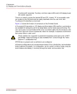
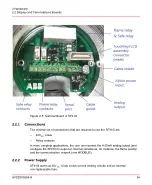
Touchkey/LCD assembly, Touchkey and three status LEDs and LCD display board
with plastic supporter
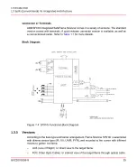
There is no need to access the internal SE and CPU boards. All the accessible parts
are located on the TB board and are easily reachable once the rear cover and
Touchkey/LCD assembly is unscrewed.
shows the location of connectors on the Terminal Board.
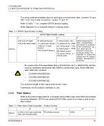
In Touchkey/LCD assembly, a LCD display and three status LEDs and four touch-buttons
are available for aiming the unit to the target flame and for local setup and tuning. The
user can access the touch-button while cover is screwed tightly into the enclosure, and
need not to open the cover to operate the button, for example, in explosive environment
that cannot allow to open cover.
Check whether the equipment is powered in hazardous area open cover is NOT
ALLOWED. Setup and tuning are also available from remote through the Flame
Explorer™ configuration tool.
SF910i has no jumpers and no switches to be configured.
All internal configurations are microprocessor-based. Once selected the communication
station address (if needed), the configuration can be carried out either locally using the
touch-buttons and display or remotely through the serial communication line.
8VZZ005286 B
33
2 Hardware
2.2 Display and Terminations Boards
Summary of Contents for Uvisor SF910i
Page 2: ......
Page 6: ......
Page 20: ...8VZZ005286 B 20...
Page 30: ...8VZZ005286 B 30...
Page 68: ...8VZZ005286 B 68...
Page 78: ...8VZZ005286 B 78...
Page 90: ...8VZZ005286 B 90...
Page 92: ...8VZZ005286 B 92...
Page 98: ...8VZZ005286 B 98...
Page 108: ...8VZZ005286 B 108...
Page 114: ...8VZZ005286 B 114...
Page 118: ...8VZZ005286 B 118...
Page 126: ...8VZZ005286 B 126...
Page 128: ...8VZZ005286 B 128...
Page 130: ...8VZZ005286 B 130...
Page 150: ...8VZZ005286 B 150...
Page 151: ...Appendix E Drawings 8VZZ005286 B 151 E Drawings...
Page 152: ...Figure E 1 Enclosure Quick Release Connector and Version LOS 8VZZ005286 B 152 E Drawings...
Page 153: ...Figure E 2 Enclosure NPT Cable Inlet and Version LOS 8VZZ005286 B 153 E Drawings...
Page 154: ...Figure E 3 Enclosure Quick Release Connector and Version FOC 8VZZ005286 B 154 E Drawings...
Page 155: ...Figure E 4 Enclosure NPT Cable Inlet and Version FOC 8VZZ005286 B 155 E Drawings...
Page 156: ...Figure E 5 FOC Flexible Assembly 8VZZ005286 B 156 E Drawings...
Page 157: ...Figure E 6 FOC Rigid Assembly 8VZZ005286 B 157 E Drawings...
Page 160: ...Figure E 9 Bailey Flame ON Standard Replacement 8VZZ005286 B 160 E Drawings...
Page 161: ...Figure E 10 Typical Bailey Flame ON Installation 8VZZ005286 B 161 E Drawings...
Page 162: ...8VZZ005286 B 162...
Page 170: ...8VZZ005286 B 170...
Page 178: ...G 7 Counter Flange 8VZZ005286 B 178 G Fittings G 7 Counter Flange...
Page 189: ......

