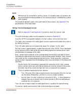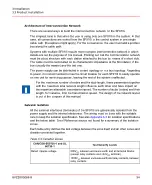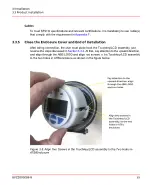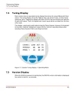
Then, the user must press the Touchkey/LCD assembly downward till to the end. If above
alignment is correct, the J11 male connector in the ATB board will be seated into the
corresponding female connector in Touchkey/LCD assembly. The user will hear or feel
the click sound between their connection. If there is some problem, do not continue to
use brutal force, otherwise the J11 male connector in the ATB board or corresponding
female connector in Touchkey/LCD assembly will be damaged. The user must snap/pull
back the Touchkey/LCD assembly, and align them again to continue.
After that, screw the circular enclosure rear cover in place and secure it with the locking
screw (2mm Allen-Key).
The threads of the cover must always be well lubricated with grease. Otherwise, the user
will not be able to open the cover in future. In case of installation in hazardous areas,
then strictly follow the instructions in
SF910i Safety Instruction Manual
(EC-DOC-G041MAN033)
, even for the relatively simple action of placing the cover in
place.
Some experience on the end of installation:
–
After wiring, screw the circular enclosure rear cover into aluminum body. Normally,
there is a designed space between the cover glass and touch button. However, if
there is an abnormal, for example, flashing LCD display, it may be due to the space
between the cover glass and touch button is too small. The user could have a try
to screw the cover back a little (< 1mm).
–
Grounding terminal of enclosure shall be connected to a good grounding point in
site to ensure touch key proper detection/operation.
–
After the user screw back/ahead the cover every time, suggest to re-power on/reset
the SF910i, since that internal circuit will re-calibrate the touch-button
identification/sensitivity after powering on.
–
Suggest to use volar pad of thumb to touch ▼ or ▲ (
Downward
/
Upward
) button,
especially due to that ▼ (
Downward
button) is near to the enclosure edge, using
the use volar pad of thumb would increase the touching area.
–
If the site of installation is not hazardous area, the unit can be powered on while the
cover is still open.
8VZZ005286 B
56
3 Installation
3.3 Product Installation
Summary of Contents for Uvisor SF910i
Page 2: ......
Page 6: ......
Page 20: ...8VZZ005286 B 20...
Page 30: ...8VZZ005286 B 30...
Page 68: ...8VZZ005286 B 68...
Page 78: ...8VZZ005286 B 78...
Page 90: ...8VZZ005286 B 90...
Page 92: ...8VZZ005286 B 92...
Page 98: ...8VZZ005286 B 98...
Page 108: ...8VZZ005286 B 108...
Page 114: ...8VZZ005286 B 114...
Page 118: ...8VZZ005286 B 118...
Page 126: ...8VZZ005286 B 126...
Page 128: ...8VZZ005286 B 128...
Page 130: ...8VZZ005286 B 130...
Page 150: ...8VZZ005286 B 150...
Page 151: ...Appendix E Drawings 8VZZ005286 B 151 E Drawings...
Page 152: ...Figure E 1 Enclosure Quick Release Connector and Version LOS 8VZZ005286 B 152 E Drawings...
Page 153: ...Figure E 2 Enclosure NPT Cable Inlet and Version LOS 8VZZ005286 B 153 E Drawings...
Page 154: ...Figure E 3 Enclosure Quick Release Connector and Version FOC 8VZZ005286 B 154 E Drawings...
Page 155: ...Figure E 4 Enclosure NPT Cable Inlet and Version FOC 8VZZ005286 B 155 E Drawings...
Page 156: ...Figure E 5 FOC Flexible Assembly 8VZZ005286 B 156 E Drawings...
Page 157: ...Figure E 6 FOC Rigid Assembly 8VZZ005286 B 157 E Drawings...
Page 160: ...Figure E 9 Bailey Flame ON Standard Replacement 8VZZ005286 B 160 E Drawings...
Page 161: ...Figure E 10 Typical Bailey Flame ON Installation 8VZZ005286 B 161 E Drawings...
Page 162: ...8VZZ005286 B 162...
Page 170: ...8VZZ005286 B 170...
Page 178: ...G 7 Counter Flange 8VZZ005286 B 178 G Fittings G 7 Counter Flange...
Page 189: ......

