


Since it strongly depend on the general cleanness of the environment, no cleaning
schedule is given here.
Version equipped with a lens (Line Of Sight versions) might require a cleaning of the
lens itself in the following cases:
–
The purging air is not clean.
–
The purging air system is non-working for a period of time.
Proceed with the following steps:
1.
Read all the warnings at the beginning of this section, refer to
SF910i Safety
Instruction Manual (EC-DOC-G041MAN033)
.
2.
Turn-off the power supply.
3.
Close the manual isolating valve (where provided).
4.
Loose the thermal union and remove the unit.
5.
Clean the scanner lens. Use degreases liquid. Do not use abrasive tools. Let it dry.
6.
Relocate the unit to the mounting (thermal union).
7.
Open the manual isolating valve.
8.
Turn-on power supply.
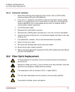
18.3 Fiber Optic Maintenance
Maintenance of the fiber optic assembly when present is given in the following procedures:
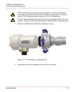
1.
Read all the warnings at the beginning of this section, refer to
SF910i Safety
Instruction Manual (EC-DOC-G041MAN033)
.
2.
Turn-off the power supply (optional).
3.
Loose the locking ferrule and remove the unit.
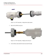
4.
Withdraw the inner carrier.
5.
In case, the fiber optic needs replacement or focal length adjustments, follow
next.
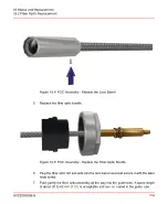
6.
Clean the lens. Use degreaser liquid. Do not use abrasive tools/substances. Let it
dry.
8VZZ005286 B
116
18 Maintenance/Cleaning/Inspection
18.3 Fiber Optic Maintenance
Summary of Contents for Uvisor SF910i
Page 2: ......
Page 6: ......
Page 20: ...8VZZ005286 B 20...
Page 30: ...8VZZ005286 B 30...
Page 68: ...8VZZ005286 B 68...
Page 78: ...8VZZ005286 B 78...
Page 90: ...8VZZ005286 B 90...
Page 92: ...8VZZ005286 B 92...
Page 98: ...8VZZ005286 B 98...
Page 108: ...8VZZ005286 B 108...
Page 114: ...8VZZ005286 B 114...
Page 118: ...8VZZ005286 B 118...
Page 126: ...8VZZ005286 B 126...
Page 128: ...8VZZ005286 B 128...
Page 130: ...8VZZ005286 B 130...
Page 150: ...8VZZ005286 B 150...
Page 151: ...Appendix E Drawings 8VZZ005286 B 151 E Drawings...
Page 152: ...Figure E 1 Enclosure Quick Release Connector and Version LOS 8VZZ005286 B 152 E Drawings...
Page 153: ...Figure E 2 Enclosure NPT Cable Inlet and Version LOS 8VZZ005286 B 153 E Drawings...
Page 154: ...Figure E 3 Enclosure Quick Release Connector and Version FOC 8VZZ005286 B 154 E Drawings...
Page 155: ...Figure E 4 Enclosure NPT Cable Inlet and Version FOC 8VZZ005286 B 155 E Drawings...
Page 156: ...Figure E 5 FOC Flexible Assembly 8VZZ005286 B 156 E Drawings...
Page 157: ...Figure E 6 FOC Rigid Assembly 8VZZ005286 B 157 E Drawings...
Page 160: ...Figure E 9 Bailey Flame ON Standard Replacement 8VZZ005286 B 160 E Drawings...
Page 161: ...Figure E 10 Typical Bailey Flame ON Installation 8VZZ005286 B 161 E Drawings...
Page 162: ...8VZZ005286 B 162...
Page 170: ...8VZZ005286 B 170...
Page 178: ...G 7 Counter Flange 8VZZ005286 B 178 G Fittings G 7 Counter Flange...
Page 189: ......


