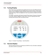


9.4
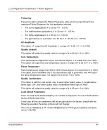
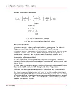
Frequency Sensitivity
Frequency sensitivity impacts the Flicker-Frequency measurement.
The higher the frequency sensitivity setting, the lower the measured Flicker-Frequency.
Frequency sensitivity is adjustable in increments of 1, between a low of 5 and a maximum
of 100. The highest Flicker-Frequency will be measured at a setting of 5 and the lowest
Flicker-Frequency at a setting of 100.
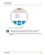
9.4.1
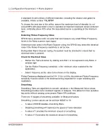
Accounting for Background Light
In some applications, the change in Flicker-Frequency resulting from a change in
frequency sensitivity may be different for light in the background when compared to the
burner flame.
In these applications, the frequency sensitivity function can be used to maximize the
difference between burner ON and burner OFF (background) Flicker-Frequencies.
SF910i is then able to discriminate between the burner flame and background light.
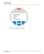
9.4.2
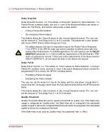
Detecting Flicker-Frequency Noise
SF910i has a precision A/D converter that is capable of measuring very small
Flicker-Frequency levels in the Flame Scanner input signal.
If electrical noise exists in the Flame Scanner wiring, the SF910i may detect the electrical
noise if the Flicker-Frequency sensitivity is set too low.
During initial Flame Scanner tuning, the system must be checked to ensure that no
electrical noise is present.
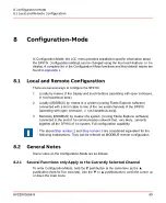
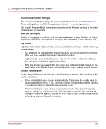
9.4.3
Check for Electrical Noise
–
Darken the Flame Scanner by making sure that it is not exposed to any flame or
ambient light.
–
Set the Flicker-Frequency sensitivity to the minimum value expected for the
application.
Flicker-Frequency displayed on the LCD must be 0 Hz. If it is not 0 Hz, the minimum
Flicker-Frequency sensitivity must be raised or the electrical wiring inspected for proper
shielding and installation.
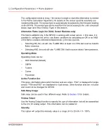
This failure as well as any other fatal failure can be recovered only by cycling the power
supply.
8VZZ005286 B
75
9 Program-Mode
9.4 Frequency Sensitivity
Summary of Contents for Uvisor SF910i
Page 2: ......
Page 6: ......
Page 20: ...8VZZ005286 B 20...
Page 30: ...8VZZ005286 B 30...
Page 68: ...8VZZ005286 B 68...
Page 78: ...8VZZ005286 B 78...
Page 90: ...8VZZ005286 B 90...
Page 92: ...8VZZ005286 B 92...
Page 98: ...8VZZ005286 B 98...
Page 108: ...8VZZ005286 B 108...
Page 114: ...8VZZ005286 B 114...
Page 118: ...8VZZ005286 B 118...
Page 126: ...8VZZ005286 B 126...
Page 128: ...8VZZ005286 B 128...
Page 130: ...8VZZ005286 B 130...
Page 150: ...8VZZ005286 B 150...
Page 151: ...Appendix E Drawings 8VZZ005286 B 151 E Drawings...
Page 152: ...Figure E 1 Enclosure Quick Release Connector and Version LOS 8VZZ005286 B 152 E Drawings...
Page 153: ...Figure E 2 Enclosure NPT Cable Inlet and Version LOS 8VZZ005286 B 153 E Drawings...
Page 154: ...Figure E 3 Enclosure Quick Release Connector and Version FOC 8VZZ005286 B 154 E Drawings...
Page 155: ...Figure E 4 Enclosure NPT Cable Inlet and Version FOC 8VZZ005286 B 155 E Drawings...
Page 156: ...Figure E 5 FOC Flexible Assembly 8VZZ005286 B 156 E Drawings...
Page 157: ...Figure E 6 FOC Rigid Assembly 8VZZ005286 B 157 E Drawings...
Page 160: ...Figure E 9 Bailey Flame ON Standard Replacement 8VZZ005286 B 160 E Drawings...
Page 161: ...Figure E 10 Typical Bailey Flame ON Installation 8VZZ005286 B 161 E Drawings...
Page 162: ...8VZZ005286 B 162...
Page 170: ...8VZZ005286 B 170...
Page 178: ...G 7 Counter Flange 8VZZ005286 B 178 G Fittings G 7 Counter Flange...
Page 189: ......


