F.2
Cabling
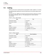
SF910i can be wired to external devices using standard cables available on the market.
The following tables specifies the technical requirement for the SF910i cables except
SF910i-L.
Note that in this case, ABB does not specify mechanical properties, global cross sections,
fire resistance properties, and so on. The following are the minimum electrical
requirements.
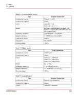
Table F.1: 24 V
DC
Power Supply
Pair
Type
1 mm
2
each
Conductor(s) section
Copper
Conductor(s) material
Conductor 1: red
Colors
Conductor 2: black
Not required
Shield
<= 20 Ohm/Km (at 20ºC)
Conductor resistance
>= 1000 MOhm x Km (at 20ºC)
Isolation resistance
< 50V
DC
Working voltage
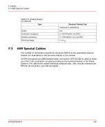
Table F.2: Relays Contacts
Three Conductors
Type
0.5mm
2
each
Conductor(s) section
Copper
Conductor(s) material
Conductor 1: Orange
Colors
Conductor 2: Light-blue
Conductor 3: Pink
Not required
Shield
<= 20 Ohm/Km (at 20ºC)
Conductor resistance
>= 1000 MOhm x Km (at 20ºC)
Isolation resistance
Up to 50V
AC
Working voltage
8VZZ005286 B
165
F Cables
F.2 Cabling
Summary of Contents for Uvisor SF910i
Page 2: ......
Page 6: ......
Page 20: ...8VZZ005286 B 20...
Page 30: ...8VZZ005286 B 30...
Page 68: ...8VZZ005286 B 68...
Page 78: ...8VZZ005286 B 78...
Page 90: ...8VZZ005286 B 90...
Page 92: ...8VZZ005286 B 92...
Page 98: ...8VZZ005286 B 98...
Page 108: ...8VZZ005286 B 108...
Page 114: ...8VZZ005286 B 114...
Page 118: ...8VZZ005286 B 118...
Page 126: ...8VZZ005286 B 126...
Page 128: ...8VZZ005286 B 128...
Page 130: ...8VZZ005286 B 130...
Page 150: ...8VZZ005286 B 150...
Page 151: ...Appendix E Drawings 8VZZ005286 B 151 E Drawings...
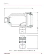
Page 152: ...Figure E 1 Enclosure Quick Release Connector and Version LOS 8VZZ005286 B 152 E Drawings...
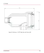
Page 153: ...Figure E 2 Enclosure NPT Cable Inlet and Version LOS 8VZZ005286 B 153 E Drawings...
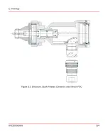
Page 154: ...Figure E 3 Enclosure Quick Release Connector and Version FOC 8VZZ005286 B 154 E Drawings...
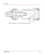
Page 155: ...Figure E 4 Enclosure NPT Cable Inlet and Version FOC 8VZZ005286 B 155 E Drawings...
Page 156: ...Figure E 5 FOC Flexible Assembly 8VZZ005286 B 156 E Drawings...
Page 157: ...Figure E 6 FOC Rigid Assembly 8VZZ005286 B 157 E Drawings...
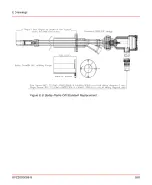
Page 160: ...Figure E 9 Bailey Flame ON Standard Replacement 8VZZ005286 B 160 E Drawings...
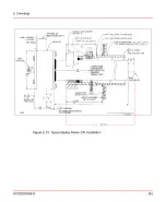
Page 161: ...Figure E 10 Typical Bailey Flame ON Installation 8VZZ005286 B 161 E Drawings...
Page 162: ...8VZZ005286 B 162...
Page 170: ...8VZZ005286 B 170...
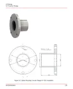
Page 178: ...G 7 Counter Flange 8VZZ005286 B 178 G Fittings G 7 Counter Flange...
Page 189: ......

