


16
Troubleshooting
This section addresses the troubleshooting of SF910i in two parts. The first applies to
the Line-Of-Sight version (LOS) also called “Direct View”, and the second applies to the
Fiber Optic Cable (FOC) version.
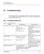
16.1 Troubleshooting LOS
Table 16.1: Troubleshooting LOS
Corrective Actions
Possible Causes
Problem
Loose the swivel flange and aim the
scanner properly
Scanner is not aimed on the target
flame
SF910i does not sense the flame
Ask for the authorized personnel to
take actions
Combustion is bad
Wrong wiring to the scanner
Check wiring
Lens is dirty
Make sure that the cooling/purging
air matches the requirements, and
follow the maintenance instruction
for cleaning
Electronics boards failure
Replace the unit
Change or confirm the factory default
setting and store it
Device is in “First Time Power Up”
Wrong wiring to the scanner
Flame is detected but the flame relay
does not energize
Check wiring
Flame-relay contact failure
Replace the device
Find out the error code in
Hardware failure (?)
Error code on display
Cycle SF910i power -OFF and then
-ON. If the error recurs, then decide
if the unit needs to be replaced or if
the cause can be external
Review SF910i connection earlier on
this manual and make wiring
congruent with serial converter
outputs
Rx/Tx +/- polarity reversed on ATB
or RS485 line converter
RS232/RS485 serial line converter
driver not installed or not compatible
with the PC-WIN OS running Flame
Explorer
SF910i device does not exchange
data with Flame Explorer
8VZZ005286 B
105
16 Troubleshooting
16.1 Troubleshooting LOS
Summary of Contents for Uvisor SF910i
Page 2: ......
Page 6: ......
Page 20: ...8VZZ005286 B 20...
Page 30: ...8VZZ005286 B 30...
Page 68: ...8VZZ005286 B 68...
Page 78: ...8VZZ005286 B 78...
Page 90: ...8VZZ005286 B 90...
Page 92: ...8VZZ005286 B 92...
Page 98: ...8VZZ005286 B 98...
Page 108: ...8VZZ005286 B 108...
Page 114: ...8VZZ005286 B 114...
Page 118: ...8VZZ005286 B 118...
Page 126: ...8VZZ005286 B 126...
Page 128: ...8VZZ005286 B 128...
Page 130: ...8VZZ005286 B 130...
Page 150: ...8VZZ005286 B 150...
Page 151: ...Appendix E Drawings 8VZZ005286 B 151 E Drawings...
Page 152: ...Figure E 1 Enclosure Quick Release Connector and Version LOS 8VZZ005286 B 152 E Drawings...
Page 153: ...Figure E 2 Enclosure NPT Cable Inlet and Version LOS 8VZZ005286 B 153 E Drawings...
Page 154: ...Figure E 3 Enclosure Quick Release Connector and Version FOC 8VZZ005286 B 154 E Drawings...
Page 155: ...Figure E 4 Enclosure NPT Cable Inlet and Version FOC 8VZZ005286 B 155 E Drawings...
Page 156: ...Figure E 5 FOC Flexible Assembly 8VZZ005286 B 156 E Drawings...
Page 157: ...Figure E 6 FOC Rigid Assembly 8VZZ005286 B 157 E Drawings...
Page 160: ...Figure E 9 Bailey Flame ON Standard Replacement 8VZZ005286 B 160 E Drawings...
Page 161: ...Figure E 10 Typical Bailey Flame ON Installation 8VZZ005286 B 161 E Drawings...
Page 162: ...8VZZ005286 B 162...
Page 170: ...8VZZ005286 B 170...
Page 178: ...G 7 Counter Flange 8VZZ005286 B 178 G Fittings G 7 Counter Flange...
Page 189: ......


