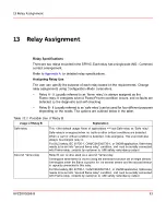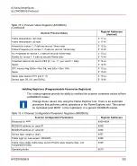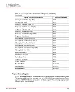
Table 15.3: Process Value Registers (MODBUS)
(Continued)
Register Addresses
(decimal)
Scanner Process Values
5111 Lo
Flame temperature high byte
5111 Hi
Flame temperature low byte
5112 Lo
Intensity for sensor 1, if safe as second Flame-relay
5112 Hi
Flicker-Frequency for sensor 1, if safe as second Flame-relay
5113 Lo
AC-Amplitude for sensor 1, if safe as second Flame-relay
5113 Hi
Quality for sensor 1, if safe as second Flame-relay
5114 Lo
Collected data can be sent to FEX (0 = no, 1 = yes, and 2 = stop)
5114 Hi
Spare
5115 Lo
DTC version flag (0x0a = Rev 04L and 0x0e = Rev 004)
5115 Hi
Spare
5118 Lo
Spare (also spares 5116 and 5117)
5118 Hi
Sensor type (IR, UV, and DUAL)
Holding Registers (Programmable Parameter Registers)
The holding registers provide the ability to read/set the scanner parameter values to/from
a MODBUS master.
Change these values only using the Flame Explorer tool. There is an automatic
procedure that performs safety operations in the Flame Explorer tool. This cannot
be replicated (and MUST not be replicated) on a generic MODBUS master.
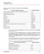
Table 15.4: Channel Configuration Parameter Registers (MODBUS)
Register Addresses
Scanner Configuration Parameters
4000-4004
Reserved for ABB
4005
MODBUS address on serial #1
4006
MODBUS address on serial #2
4007
Sensor type (single or dual)
4008
Flame logic on dual sensor (OR/AND)
4009
Flame-relay usage (Safe-relay, second Flame-relay, Quality-relay, and
Temperature-relay)
4010
Operating mode
8VZZ005286 B
102
15 Serial Interfaces
15.2 MODBUS Protocol
Summary of Contents for Uvisor SF910i
Page 2: ......
Page 6: ......
Page 20: ...8VZZ005286 B 20...
Page 30: ...8VZZ005286 B 30...
Page 68: ...8VZZ005286 B 68...
Page 78: ...8VZZ005286 B 78...
Page 90: ...8VZZ005286 B 90...
Page 92: ...8VZZ005286 B 92...
Page 98: ...8VZZ005286 B 98...
Page 108: ...8VZZ005286 B 108...
Page 114: ...8VZZ005286 B 114...
Page 118: ...8VZZ005286 B 118...
Page 126: ...8VZZ005286 B 126...
Page 128: ...8VZZ005286 B 128...
Page 130: ...8VZZ005286 B 130...
Page 150: ...8VZZ005286 B 150...
Page 151: ...Appendix E Drawings 8VZZ005286 B 151 E Drawings...
Page 152: ...Figure E 1 Enclosure Quick Release Connector and Version LOS 8VZZ005286 B 152 E Drawings...
Page 153: ...Figure E 2 Enclosure NPT Cable Inlet and Version LOS 8VZZ005286 B 153 E Drawings...
Page 154: ...Figure E 3 Enclosure Quick Release Connector and Version FOC 8VZZ005286 B 154 E Drawings...
Page 155: ...Figure E 4 Enclosure NPT Cable Inlet and Version FOC 8VZZ005286 B 155 E Drawings...
Page 156: ...Figure E 5 FOC Flexible Assembly 8VZZ005286 B 156 E Drawings...
Page 157: ...Figure E 6 FOC Rigid Assembly 8VZZ005286 B 157 E Drawings...
Page 160: ...Figure E 9 Bailey Flame ON Standard Replacement 8VZZ005286 B 160 E Drawings...
Page 161: ...Figure E 10 Typical Bailey Flame ON Installation 8VZZ005286 B 161 E Drawings...
Page 162: ...8VZZ005286 B 162...
Page 170: ...8VZZ005286 B 170...
Page 178: ...G 7 Counter Flange 8VZZ005286 B 178 G Fittings G 7 Counter Flange...
Page 189: ......

