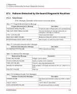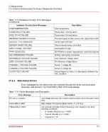
Table 17.5: Hardware Circuitry Error Messages
(Continued)
Description
Hardware Circuitry Error Messages
Over temperature
OVERTEMPERATURE
Flame-relay 1 driving failure
FLAME RELAY FAILURE
Flame-relay 2 driving failure
SAFE RELAY FAILURE
The input signal of both sensors are higher than 2.45V
SENSORS VALUES TOO HIGH
Sensor type unknown
SENSOR TYPE UNKNOWN
Check internal sensor short fault
SENSOR SHORT FAILURE
Input signal too high
INPUT SIGNAL TOO HIGH
EEPROM is no longer responding to read/write requests
FRAM DEADLOCK
Analog input wrong conversion
A/D CONVERSION FAILURE
2.5V reference voltage failure
REFERENCE VOLTAGE FAILURE
0V reference voltage failure
ZERO VOLTAGE FAILURE
Sensor 1 voltage fail
CHANNEL 1 VOLTAGE FAILURE
Sensor 2 voltage fail
CHANNEL 2 VOLTAGE FAILURE
Wrong frequency: there is a discrepancy between the
CPU oscillator
CLOCK TEST FAILURE
17.1.2 Non-Fatal Errors
Error messages for non-fatal errors are reported through the serial communication
channels, and stored in the Fault History field of the local display.
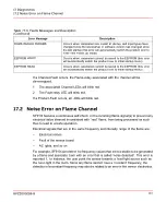
Table 17.6: Faults Messages and Description
Description
Error Message
Low-voltage input and low Flicker-Frequency (less than 5 Hz) [Safe Flame
only]
NO INPUT SIGNAL
High voltage limit reached [Safe Flame, 4 to 20 ma]
HIGH INPUT LIMIT
Low intensity and high Flicker-Frequency error, based on the three
following conditions:
FREQUENCY HIGH
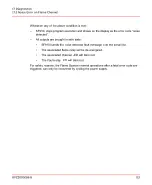
–
If Intensity Drop-Out is > 3 AND
–
Current Intensity is <= 3 AND
–
Frequency > 98
8VZZ005286 B
111
17 Diagnostics
17.1 Failures Detected by On-board Diagnostic Routines
Summary of Contents for Uvisor SF910i
Page 2: ......
Page 6: ......
Page 20: ...8VZZ005286 B 20...
Page 30: ...8VZZ005286 B 30...
Page 68: ...8VZZ005286 B 68...
Page 78: ...8VZZ005286 B 78...
Page 90: ...8VZZ005286 B 90...
Page 92: ...8VZZ005286 B 92...
Page 98: ...8VZZ005286 B 98...
Page 108: ...8VZZ005286 B 108...
Page 114: ...8VZZ005286 B 114...
Page 118: ...8VZZ005286 B 118...
Page 126: ...8VZZ005286 B 126...
Page 128: ...8VZZ005286 B 128...
Page 130: ...8VZZ005286 B 130...
Page 150: ...8VZZ005286 B 150...
Page 151: ...Appendix E Drawings 8VZZ005286 B 151 E Drawings...
Page 152: ...Figure E 1 Enclosure Quick Release Connector and Version LOS 8VZZ005286 B 152 E Drawings...
Page 153: ...Figure E 2 Enclosure NPT Cable Inlet and Version LOS 8VZZ005286 B 153 E Drawings...
Page 154: ...Figure E 3 Enclosure Quick Release Connector and Version FOC 8VZZ005286 B 154 E Drawings...
Page 155: ...Figure E 4 Enclosure NPT Cable Inlet and Version FOC 8VZZ005286 B 155 E Drawings...
Page 156: ...Figure E 5 FOC Flexible Assembly 8VZZ005286 B 156 E Drawings...
Page 157: ...Figure E 6 FOC Rigid Assembly 8VZZ005286 B 157 E Drawings...
Page 160: ...Figure E 9 Bailey Flame ON Standard Replacement 8VZZ005286 B 160 E Drawings...
Page 161: ...Figure E 10 Typical Bailey Flame ON Installation 8VZZ005286 B 161 E Drawings...
Page 162: ...8VZZ005286 B 162...
Page 170: ...8VZZ005286 B 170...
Page 178: ...G 7 Counter Flange 8VZZ005286 B 178 G Fittings G 7 Counter Flange...
Page 189: ......

