Advanced Videographic Recorder
SM2000
4 CONFIGURATION
IM/SM2000
Issue 11
97
4.7.4 Ethernet Modules
Refer to the
Ethernet Communications Option User Guide Supplement
(
IM/SMENET
) for information on how to install, configure and
use the instrument on an Ethernet network and for information on configuring and using the e-mail facility.
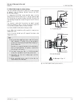
4.8 Modbus TCP
Modbus TCP enables Modbus devices to communicate via an ethernet network transferring Modbus messages via TCP/IP.
Communication with standard, serially connected, Modbus RTU devices is also possible through a Modbus TCP Gateway.
Refer to the
Ethernet Communications Option User Guide Supplement
(
IM/SMENET
) for information on how to install, configure and
use the instrument on an Ethernet network and for information on configuring and using Modbus TCP facility.
Refer to Appendix B, page 110 for further information on using the Modbus link.
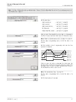
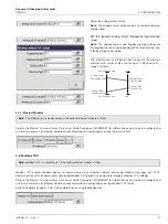
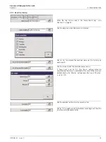
Select the analog output source.
Note.
The analog output source can be any internal or external
analog signal.
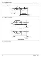
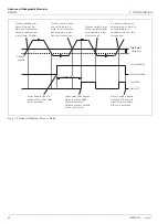
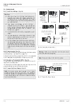
Set the required analog output engineering and electrical
ranges.
Note.
The 'Engineering low' and 'Engineering high' settings are
the engineering values corresponding to the 'Electrical low' and
'Electrical high' values below.
The 'Electrical low' and 'Electrical high' values are the minimum
and maximum values of the current output, in Electrical units –
range 0 to 23mA.
Note.
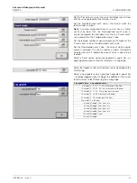
The Ethernet tab is displayed only if the optional ethernet module is fitted.
Note.
Modbus TCP is available only if the optional ethernet module is fitted.
Analog Output
Engineering High
21mA
0mA
Analog Output
Engineering Low
Analog Output
Electrical High
Analog Output
Electrical Low
Source Range High
Source Range Low


