Advanced Videographic Recorder
SM2000
5 INSTALLATION
IM/SM2000
Issue 11
107
5.8 Hybrid I/O Module Connections
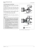
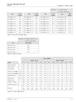
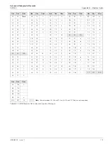
5.8.1 Digital Output Connections – Fig. 5.12
Six digital outputs are provided on the Hybrid option board.
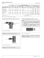
5.8.2 Digital Input Connections – Fig. 5.13
Six digital inputs are provided on Hybrid option boards.
5.8.3 Analog Output Connections – Fig. 5.14
Two analog outputs are provided on the Hybrid option board.
Fig. 5.12 Digital Output Connections
Note.
Voltage level: 5V.
Load:
450
Ω
min.
15k
Ω
max.
Digital Output
Common
Load
9
10
11
12
13
14
15
16
do1
do2
do3
do4
do5
do6
COM
COM
Fig. 5.13 Digital Input Connections
Fig. 5.14 Analog Output Connections
di1
di2
di3
di4
di5
di6
COM
COM
Terminal Blocks C or D
Input State
Dxx active
Switch Input
(volt-free)
or
or
5V
0V
Logic Input
(TTL)
Logic State
Dxx inactive
1
2
3
4
5
6
7
8
5V
or
0V
a01
a02
17
18
19
20
+
+


