Advanced Videographic Recorder
SM2000
2 OPERATION
IM/SM2000
Issue 11
15
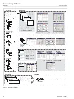
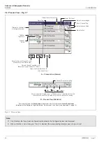
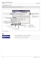
2.4 Bargraph Views – Fig. 2.5
Fig. 2.5 Bargraph Views
A Vertical Bargraph View
Alarm Trip Level
(not shown for slow and
fast rate alarms)
Digital Channel
Maximum Value
(solid color)
Minimum Value
(white fill)
Instantaneous Value
Engineering Range
Middle Value
Digital On or Off tag,
according to input status
Engineering Range
High Value
Engineering Range
Low Value
Short Channel Tag
Current Value
Alarm Event Icon
see Rear fold-out
Engineering Units
Status Icons
Identical Maximum and Minimum Values
Minimum below engineering limit,
maximum above engineering limit
Selects the next Process Group
(if enabled) or Status View
Selects the next enabled view in the group
(Digital Indicator, Process or Chart)
Opens the Operator Menu for
the current view
B Horizontal Bargraph View
Alarm Trip Level
(not shown for slow and
fast rate alarms)
Global Alarm Status Icon
Maximum Value
(solid color)
Short Channel Tag
Minimum Value
(white fill)
Alarm Event Icon
Instantaneous
Value
Engineering Range
Middle Value
Engineering Range
High Value
Engineering Range
Low Value
Current Value
Identical Maximum
and Minimum Values
Minimum below
engineering limit,
Maximum above
engineering limit
For a description of the
Status Icons
(displayed in the Status Bar) and
Alarm Event Icons
(displayed in the Bargraph, Digital Indicators, Process and Chart Views), see Appendix G, page 131.


