Advanced Videographic Recorder
SM2000
4 CONFIGURATION
94
IM/SM2000
Issue 11
4.7 I/O Module Configuration
4.7.1 Analog Inputs
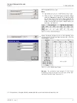
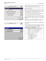
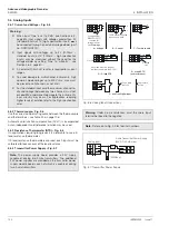
Fig. 4.16 I/O Module Configuration
Note.
The instrument detects the type of module fitted in each position automatically.
Set the mains rejection frequency used to electrical noise
induced on the signal lines by power supply cables.
I
nput Adjustment
Manually fine-tune inputs to remove process offset errors or
system scale errors.
Note.
Input adjustment frames appear only if recording is
enabled during configuration, i.e. the 'Disable recording in
configuration' check box is
not
ticked on entry to the
Configuration level – see Fig. 4.1, page 46.
Changes to the Analog Input Type (see Section 4.6.2,
page 80) must be saved to the current configuration
before commencing input adjustment.
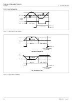
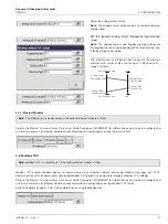
Actual value / Desired value
1. Adjust the process or simulated input signal to a known
value below 50% of the engineering range.
2. If 'Actual value' (in engineering units) is different from
expected, set 'Desired value' to the correct value ('Offset
adjust' and 'Span adjust' values are calculated
automatically).
3. Repeat steps 1 and 2 for a value above 50% of the
engineering range.
4. Repeat steps 1 to 3 for each input.
Reset adjustment
Select to reset 'Offset adjust' and 'Span adjust' (see next page)
to zero and to 1 respectively.
I/O
Modules


