44
Configurable logic blocks (CL1)
Chapter 3
Common functions
6
Configurable logic blocks (CL1)
6.1
Application
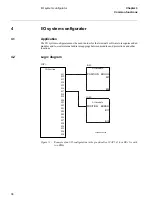
The user can with the available logic function blocks build logic functions and configure the ter-
minal to meet application specific requirements.
Different protection, control, and monitoring functions within the REx 5xx terminals are quite
independent as far as their configuration in the terminal is concerned. The user can not change
the basic algorithms for different functions. But these functions combined with the logic func-
tion blocks can be used to create application specific functionality.
6.2
Inverter function block (INV)
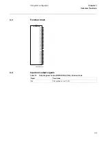
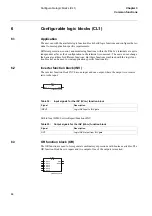
The inverter function block INV has one input and one output, where the output is in inverse
ratio to the input.
Table 34:
Input signals for the INV (IVnn-) function block
Path in local HMI: ServiceReport/Functions/INV
Table 35:
Output signals for the INV (IVnn-) function block
6.3
OR function block (OR)
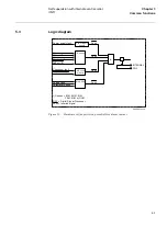
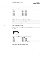
The OR function is used to form general combinatory expressions with boolean variables. The
OR function block has six inputs and two outputs. One of the outputs is inverted.
Signal
Description
INPUT
Logic INV-Input to INV gate
Signal
Description
OUT
Logic INV-Output from INV gate
xx00000158.vsd
IV01-
INV
INPUT
OUT
xx00000159.vsd
O001-
OR
INPUT1
INPUT2
INPUT3
INPUT4
INPUT5
INPUT6
OUT
NOUT
Summary of Contents for REL 501-C1 2.5
Page 1: ...Technical reference manual Line distance protection terminal REL 501 C1 2 5 ...
Page 2: ......
Page 26: ...14 Introduction to the technical reference manual Chapter 1 Introduction ...
Page 42: ...30 Technical data Chapter 2 General ...
Page 66: ...54 Blocking of signals during test BST Chapter 3 Common functions ...
Page 142: ...130 Time delayed overvoltage protection TOV Chapter 6 Voltage ...
Page 162: ...150 Autorecloser AR Chapter 9 Control ...
Page 174: ...162 Event function EV Chapter 10 Logic ...
Page 210: ...198 Serial communication Chapter 12 Data communication ...
Page 226: ...214 Serial communication modules SCM Chapter 13 Hardware modules ...
Page 230: ...218 Terminal diagrams Chapter 14 Diagrams Figure 87 REL 501 C1 with DC switch ...
Page 234: ...222 Terminal diagrams Chapter 14 Diagrams ...
Page 237: ......


