208
Binary output module (BOM)
Chapter 13
Hardware modules
6.3
Function block
Figure 82:
Binary output module
6.4
Input and output signals
Table 217: Input signals for binary output module BOM
Path in local HMI: ServiceReport/I/O/Slotnn-BOMn/FuncOutputs
Table 218: Output signals for binary output module BOM
BOM
POSITION
ERROR
BONAME01
BONAME02
BONAME03
BONAME04
BONAME05
BONAME06
BONAME07
BONAME08
BONAME09
BONAME10
BONAME11
BONAME12
BONAME13
BONAME14
BONAME15
BONAME16
BONAME17
BONAME18
BONAME19
BONAME20
BONAME21
BONAME22
BONAME23
BONAME24
BO1
BO2
BO3
BO4
BO5
BO6
BO7
BO8
BO9
BO10
BO11
BO12
BO13
BO14
BO15
BO16
BO17
BO18
BO19
BO20
BO21
BO22
BO23
BO24
BLKOUT
xx00000156.vsd
Signal
Description
POSITION
I/O module slot position
BO1-BO24
Binary output data
BLKOUT
Block output signals
BONAME01-BONAME24
Output name string settings
Signal
Description
ERROR
Binary module fail
Summary of Contents for REL 501-C1 2.5
Page 1: ...Technical reference manual Line distance protection terminal REL 501 C1 2 5 ...
Page 2: ......
Page 26: ...14 Introduction to the technical reference manual Chapter 1 Introduction ...
Page 42: ...30 Technical data Chapter 2 General ...
Page 66: ...54 Blocking of signals during test BST Chapter 3 Common functions ...
Page 142: ...130 Time delayed overvoltage protection TOV Chapter 6 Voltage ...
Page 162: ...150 Autorecloser AR Chapter 9 Control ...
Page 174: ...162 Event function EV Chapter 10 Logic ...
Page 210: ...198 Serial communication Chapter 12 Data communication ...
Page 226: ...214 Serial communication modules SCM Chapter 13 Hardware modules ...
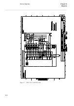
Page 230: ...218 Terminal diagrams Chapter 14 Diagrams Figure 87 REL 501 C1 with DC switch ...
Page 234: ...222 Terminal diagrams Chapter 14 Diagrams ...
Page 237: ......


