4
Introduction to the technical reference manual
Chapter 1
Introduction
Figure 2:
Simplified logic diagram example
The names of the configurable logic signals consist of two parts divided by dashes. The first part
consists of up to four letters and presents the abbreviated name for the corresponding function.
The second part presents the functionality of the particular signal. According to this explanation,
the meaning of the signal TUV--BLKTR is as follows.
•
The first part of the signal, TUV- represents the adherence to the Time delayed
Under-Voltage function.
•
The second part of the signal name, BLKTR informs the user that the signal will
BLocK the TRip from the under-voltage function, when its value is a logical one
(1).
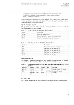
Different binary signals have special symbols with the following significance:
•
Signals drawn to the box frame to the left present functional input signals. It is
possible to configure them to functional output signals of other functions as well
as to binary input terminals of the REx 5xx terminal. Examples are TUV--BLK-
TR, TUV--BLOCK and TUV--VTSU. Signals in frames with a shaded area on
their right side present the logical setting signals. Their values are high (1) only
when the corresponding setting parameter is set to the symbolic value specified
within the frame. Example is the signal Operation = On. These signals are not
configurable. Their logical values correspond automatically to the selected set-
ting value.The internal signals are usually dedicated to a certain function. They
are normally not available for configuration purposes. Examples are signals
STUL1, STUL2 and STUL3.The functional output signals, drawn to the box
frame to the right, present the logical outputs of functions and are available for
TUV--BLKTR
TUV--BLOCK
TUV--VTSU
>1
STUL1
STUL2
&
&
&
STUL3
Operation = On
>1
&
t
t
t
15 ms
TUV--TRIP
TUV--START
TUV--STL1
TUV--STL2
TUV--STL3
t
15 ms
t
15 ms
t
15 ms
t
15 ms
TRIP - cont.
xx01000170.vsd
Summary of Contents for REL 501-C1 2.5
Page 1: ...Technical reference manual Line distance protection terminal REL 501 C1 2 5 ...
Page 2: ......
Page 26: ...14 Introduction to the technical reference manual Chapter 1 Introduction ...
Page 42: ...30 Technical data Chapter 2 General ...
Page 66: ...54 Blocking of signals during test BST Chapter 3 Common functions ...
Page 142: ...130 Time delayed overvoltage protection TOV Chapter 6 Voltage ...
Page 162: ...150 Autorecloser AR Chapter 9 Control ...
Page 174: ...162 Event function EV Chapter 10 Logic ...
Page 210: ...198 Serial communication Chapter 12 Data communication ...
Page 226: ...214 Serial communication modules SCM Chapter 13 Hardware modules ...
Page 230: ...218 Terminal diagrams Chapter 14 Diagrams Figure 87 REL 501 C1 with DC switch ...
Page 234: ...222 Terminal diagrams Chapter 14 Diagrams ...
Page 237: ......


