186
Serial communication
Chapter 12
Data communication
•
Time synchronization
The events created in the terminal available for the IEC protocol are based on the event function
blocks EV01 - EV06 and disturbance function blocks DRP1 - DRP3. The commands are repre-
sented in a dedicated function block ICOM. This block has output signals according to the IEC
protocol for all commands.
1.5.3
IEC 60870-5-103
The tables below specifies the information types supported by the REx 5xx products with the
communication protocol IEC 60870-5-103 implemented.
To support the information, corresponding functions must be included in the protection terminal.
There are no representation for the following parts:
•
Generating events for test mode
•
Cause of transmission: Info no 11, Local operation
Glass or plastic fibre should be used for the optical ports. BFOC2.5 is the recommended inter-
face to use (BFOC2.5 is the same as ST connectors). ST connectors are used with the optical
power as specified in standard, please see the Installation and commissioning manual.
For the galvanic interface RS485, use terminated network according to EIA Standard RS-485.
The modem contact for the cable is Phoenix MSTB2.5/6-ST-5.08 1757051.
For more information please see the IEC standard IEC 60870-5-103.
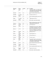
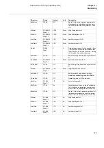
Table 183: Information numbers in monitoring direction
Info no
Message
Supported
2
Reset FCB
Yes
3
Reset CU
Yes
4
Start/restart
Yes
5
Power on
No
16
Autorecloser active
Yes
17
Teleprotection active
Yes
18
Protection active
Yes
19
LED reset
Yes
20
Information blocking
Yes
21
Test mode
No
22
Local parameter setting
No
23
Characteristic 1
Yes
24
Characteristic 2
Yes
25
Characteristic 3
Yes
26
Characteristic 4
Yes
27
Auxiliary input 1
Yes
Summary of Contents for REL 501-C1 2.5
Page 1: ...Technical reference manual Line distance protection terminal REL 501 C1 2 5 ...
Page 2: ......
Page 26: ...14 Introduction to the technical reference manual Chapter 1 Introduction ...
Page 42: ...30 Technical data Chapter 2 General ...
Page 66: ...54 Blocking of signals during test BST Chapter 3 Common functions ...
Page 142: ...130 Time delayed overvoltage protection TOV Chapter 6 Voltage ...
Page 162: ...150 Autorecloser AR Chapter 9 Control ...
Page 174: ...162 Event function EV Chapter 10 Logic ...
Page 210: ...198 Serial communication Chapter 12 Data communication ...
Page 226: ...214 Serial communication modules SCM Chapter 13 Hardware modules ...
Page 230: ...218 Terminal diagrams Chapter 14 Diagrams Figure 87 REL 501 C1 with DC switch ...
Page 234: ...222 Terminal diagrams Chapter 14 Diagrams ...
Page 237: ......


