111
Definite time non-directional overcurrent
protection (TOC)
Chapter 5
Current
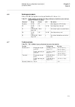
2.6
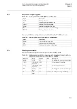
Setting parameters
Path in local HMI: Settings/Functions/Group
n
/TimeDelayOC (where
n
=1-4)
Table 117: Setting parameters for the time delayed phase and residual overcurrent pro-
tection TOC (TOC--) function
2.7
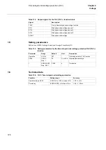
Technical data
Table 118: TOC - Definite time nondirectional overcurrent protection
Parameter
Range
Default
Unit
Description
Operation
Off, On
Off
-
Operating mode for TOC function
IP>
10-400
Step: 1
100
% of I1b
Operating phase overcurrent
tP
0.000-60.000
Step: 0.001
10.000
s
Time delay of phase overcurrent function
IN>
10-150
Step:1
100
% of I4b
Operating residual current
tN
0.000-60.000
Step: 0.001
10.000
s
Time delay of residual overcurrent func-
tion
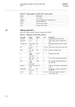
Function
Setting range
Accuracy
Operate current
Phase measuring ele-
ments, IP>
(10-400) % of I1b in
steps of 1 %
±
2.5 % of I
r
at I
≤
I
r
±
2.5 % of I at I >I
r
Residual measuring ele-
ments, IN>
(10-150) % of I4b in
steps of 1 %
±
2.5 % of I
r
at I
≤
I
r
±
2.5 % of I at I >I
r
Time delay
Phase measuring ele-
ments
(0.000-60.000) s in
steps of 1 ms
±
0.5 % of t
±
10 ms
Residual measuring ele-
ments
(0.000-60.000) s in
steps of 1 ms
±
0.5 % of t
±
10 ms
Dynamic overreach at
τ
< 100 ms
-
< 5 %
Summary of Contents for REL 501-C1 2.5
Page 1: ...Technical reference manual Line distance protection terminal REL 501 C1 2 5 ...
Page 2: ......
Page 26: ...14 Introduction to the technical reference manual Chapter 1 Introduction ...
Page 42: ...30 Technical data Chapter 2 General ...
Page 66: ...54 Blocking of signals during test BST Chapter 3 Common functions ...
Page 142: ...130 Time delayed overvoltage protection TOV Chapter 6 Voltage ...
Page 162: ...150 Autorecloser AR Chapter 9 Control ...
Page 174: ...162 Event function EV Chapter 10 Logic ...
Page 210: ...198 Serial communication Chapter 12 Data communication ...
Page 226: ...214 Serial communication modules SCM Chapter 13 Hardware modules ...
Page 230: ...218 Terminal diagrams Chapter 14 Diagrams Figure 87 REL 501 C1 with DC switch ...
Page 234: ...222 Terminal diagrams Chapter 14 Diagrams ...
Page 237: ......


