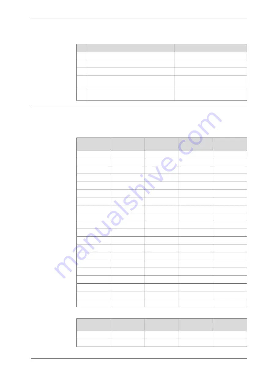
Note
Action
Under
Topics
, tap
Motion
.
3
Select
Arm
.
4
Select the mechanical unit.
5
Change the values for the parameters
Upper
joint bound
and
Lower Joint bound
.
6
Tap
OK
to save the change and then restart
the controller.
7
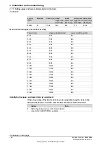
Examples of correct values for the software limits
The following tables show configuration values for
Upper Joint Bound
and
Lower
Joint Bound
for a number of different configurations
Single robot carriage and signal transfer carriage
Lower Joint
Bound
(m)
Upper Joint
Bound
(m)
Travel L (m)
Modules
Track L (mm)
-0.5
0.35
0.85
2
2230
-0.5
1.35
1.85
3
3230
-0.5
2.35
2.85
4
4230
-0.5
3.35
3.85
5
5230
-0.5
4.35
4.85
6
6230
-0.5
5.35
5.85
7
7230
-0.5
6.35
6.85
8
8230
-0.5
7.35
7.85
9
9230
-0.5
8.35
8.85
10
10230
-0.5
9.35
9.85
11
11230
-0.5
10.35
10.85
12
12230
-0.5
11.35
11.85
13
13230
-0.5
12.35
12.85
14
14230
-0.5
13.35
13.85
15
15230
-0.5
14.35
14.85
16
16230
-0.5
15.35
15.85
17
17230
-0.5
16.35
16.85
18
18230
-0.5
17.35
17.85
19
19230
-0.5
18.35
18.85
20
20230
-0.5
19.35
19.85
21
21230
Single robot carriage with extra plate
Lower Joint
Bound
(m)
Upper Joint
Bound
(m)
Travel L (m)
Modules
Total L (mm)
-0.34
1.35
1.69
4
4230
-0.34
2.35
2.69
5
5230
Continues on next page
Product manual - IRBT 2005
127
3HAC051130-001 Revision: F
© Copyright 2015 - 2018 ABB. All rights reserved.
2 Installation and commissioning
2.7.3 Setting upper and lower software limits for the track
Continued
Summary of Contents for IRBT 2005
Page 1: ...ROBOTICS Product manual IRBT 2005 ...
Page 8: ...This page is intentionally left blank ...
Page 44: ...This page is intentionally left blank ...
Page 148: ...This page is intentionally left blank ...
Page 284: ...This page is intentionally left blank ...
Page 286: ...This page is intentionally left blank ...
Page 289: ......


