ACQ550-U1 User’s Manual
111
2007
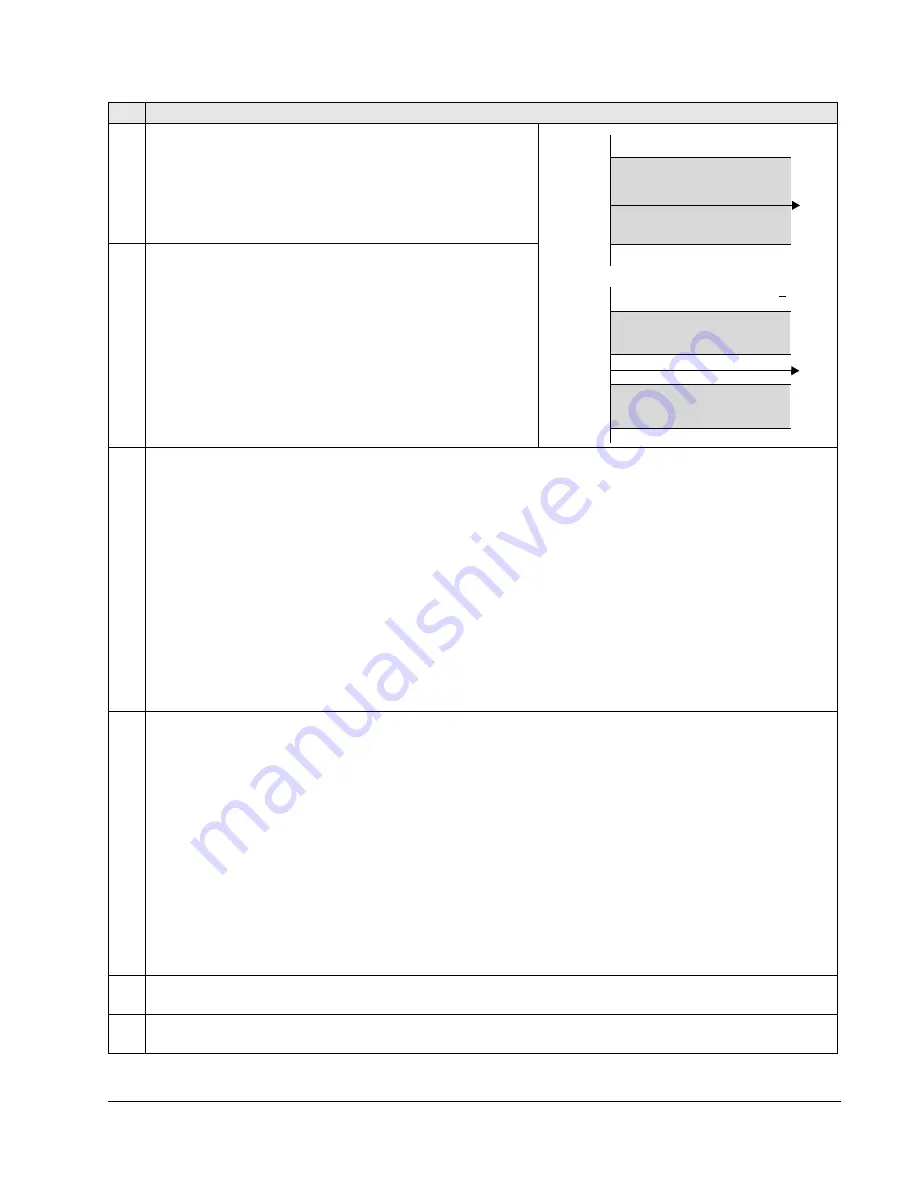
MINIMUM FREQ
Defines the minimum limit for the drive output frequency.
• A positive or zero minimum frequency value defines two
ranges, one positive and one negative.
• A negative minimum frequency value defines one speed range.
See the figure.
Note:
Keep
MINIMUM
FREQ
MAXIMUM
FREQ
.
2008
MAXIMUM FREQ
Defines the maximum limit for the drive output frequency.
2013
MIN TORQUE SEL
Defines control of the selection between two minimum torque limits (2015
MIN
TORQUE
1 and 2016
MIN
TORQUE
2).
0 =
MIN
TORQUE
1 – Selects 2015
MIN
TORQUE
1 as the minimum limit used.
1 =
DI
1 – Defines digital input
DI
1 as the control for selecting the minimum limit used.
• Activating the digital input selects
MIN
TORQUE
2 value.
• De-activating the digital input selects
MIN
TORQUE
1 value.
2…6 =
DI
2…
DI
6 – Defines digital input
DI
2…
DI
6 as the control for selecting the minimum limit used.
• See
DI
1 above.
7 =
COMM
– Defines bit 15 of the Command Word 1 as the control for selecting the minimum limit used.
• The Command Word is supplied through fieldbus communication.
• The Command Word is parameter 0301.
-1 =
DI
1(
INV
) – Defines an inverted digital input
DI
1 as the control for selecting the minimum limit used.
• Activating the digital input selects
MIN
TORQUE
1 value.
• De-activating the digital input selects
MIN
TORQUE
2 value.
-2…-6 =
DI
2(
INV
)…
DI
6(
INV
) – Defines an inverted digital input
DI
2…
DI
6 as the control for selecting the minimum limit
used.
• See
DI
1(
INV
) above.
2014
MAX TORQUE SEL
Defines control of the selection between two maximum torque limits (2017
MAX
TORQUE
1 and 2018
MAX
TORQUE
2).
0 =
MAX
TORQUE
1 – Selects 2017
MAX
TORQUE
1 as the maximum limit used.
1 =
DI
1 – Defines digital input
DI
1 as the control for selecting the maximum limit used.
• Activating the digital input selects
MAX
TORQUE
2 value.
• De-activating the digital input selects
MAX
TORQUE
1 value.
2…6 =
DI
2…
DI
6 – Defines digital input
DI
2…
DI
6 as the control for selecting the maximum limit used.
• See
DI
1 above.
7 =
COMM
– Defines bit 15 of the Command Word 1 as the control for selecting the maximum limit used.
• The Command Word is supplied through fieldbus communication.
• The Command Word is parameter 0301.
-1 =
DI
1(
INV
) – Defines an inverted digital input di1 as the control for selecting the maximum limit used.
• Activating the digital input selects
MAX
TORQUE
1 value.
• De-activating the digital input selects
MAX
TORQUE
2 value.
-2…-6 =
DI
2(
INV
)…
DI
6(
INV
) – Defines an inverted digital input
DI
2…
DI
6 as the control for selecting the maximum limit
used.
• See
DI
1(
INV
) above.
2015
MIN TORQUE 1
Sets the first minimum limit for torque (%). Value is a percent of the motor nominal torque.
2016
MIN TORQUE 2
Sets the second minimum limit for torque (%). Value is a percent of the motor nominal torque.
Code Description
P 2007
P 2008
Freq
-(P 2007)
-(P 2008)
P 2008
P 2007
Frequency range allowed
Frequency range allowed
Frequency range allowed
Time
Freq
Time
2007 value is > 0
0
0
2007 value is < 0
Summary of Contents for ACQ550-U1-011A-6
Page 1: ...ACQ550 User s Manual ACQ550 U1 Drives 1 200 hp ...
Page 4: ......
Page 10: ...10 ACS550 U1 User s Manual Table of contents ...
Page 42: ...42 ACQ550 U1 User s Manual Start up control with I O and ID Run ...
Page 56: ...56 ACQ550 U1 User s Manual Control panel ...
Page 68: ...68 ACQ550 U1 User s Manual Application macros ...
Page 250: ...250 ACQ550 U1 User s Manual Fieldbus adapter ...
Page 266: ...266 ACQ550 U1 User s Manual Maintenance ...
Page 314: ...314 ACQ550 U1 User s Manual Index ...


