


Publication No. PPC11A-HRM/1
Functional Description 63
4.23.2 External Interrupt
PCI Interrupts
Legacy PCI devices, connected via PCIe to the processor, have their interrupts
connected to their respective PCIe-PCI bridges, which convert the interrupts into
PCIe messages. These are then passed to the interrupt controller in the processor.
The internal interrupt signals that are used for this purpose in the processor are
shared with external interrupt signals as shown in the following table. For this
reason, these external interrupts are not used and are pulled high.
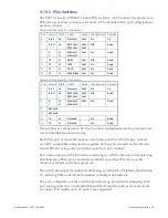
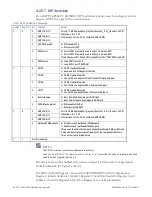
Table 4-32 Processor PCI INTx and External IRQ Sharing
PCI Interrupt External Interrupt Pin Source
Port 1 INTB
IRQ[1]
PCIe Switch
Port 1 INTC
IRQ[2]
PCIe Switch
Port 1 INTD
IRQ[3]
PCIe Switch
Port 2 INT B
IRQ[5]
VME interface
Port 2 INT C
IRQ[6]
VME interface
Port 2 INT D
IRQ[7]
VME interface
The INTA signals from the PCIe ports are routed as dedicated inputs to the Interrupt
Controller and are not shared with external pins.
FPGA Interrupts
The FPGA connects to the IRQ[0], IRQ[4] and IRQ[8:11] interrupt inputs to the
processor. These inputs are configured as active-low, level-sensitive.
The FPGA
registers provide the option to route the internal and external
interrupt sources shown below to any of these interrupt inputs under software
control:
•
Ethernet PHY
•
RTC
•
Temperature
•
GPIO
•
BMM
•
Timer
•
PCIe Switch
The processor can determine the cause of the interrupt by reading an


