


Publication No. PPC11A-HRM/1
Installation and Power Up/Reset 25
3.3
Connecting to PPC11A
To interact with on-board firmware requires the PPC11A to have, as a minimum, a
terminal connection present on the serial COM1 port. An Ethernet connection may
also be required for Host/Target interaction, depending on operating system
requirements. These ports may be accessed through the backplane pins, using a Rear
Transition Module (RTM).
COM1 is configured by default as DTE with settings of 115200 baud, 8 bits/character,
1 stop bit, parity disabled and no flow control, but this can be Bootrom dependent.
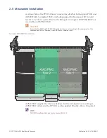
3.3.1 Rear Transition Module
For development systems, connection to the Serial and Ethernet I/O can be achieved
using an RTM. This converts the condensed pin out of the backplane connectors to
pinouts suitable for use by industry standard connectors.
The following items are required:
•
The PPC11A
•
An appropriate RTM (P0P2X605)
•
An SIOX600 breakout panel to provide two 9-way D-type connectors for
COM1/COM2
•
A null-modem 9-way D-type cable for connecting COM1 to a control terminal or
PC running terminal emulation software
•
For the Ethernet ports, a CAT5 (or better) straight-through patch cable for
10/100/1000BASE-T
The I/O Modules manual contains more details on fitting the RTM. Similar antistatic
and safety precautions apply when handling and/or installing RTMs as for the
PPC11A.
LINK
I/O Modules Hardware Reference Manual, publication number RT5154.
3.4
Reset and Power-up Sequence
A power sequencer monitors the backplane supply voltage, and holds the PPC11A
in reset or shuts down the on-board power supplies if it is not within specified
limits. The on-board power supplies are also monitored for correct operation, and
the PPC11A is prevented from powering up and held in reset if any supply fails to
operate correctly.
The green Power Good LED (DS50) is lit when all supplies are within specification.
The +5V supply to the mezzanine cards is switched, under the control of the power
manager device, so that the 5V and 3.3V supplies are applied to the mezzanines at
approximately the same time.


