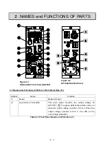
2-3
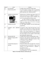
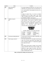
Number
Name
Function
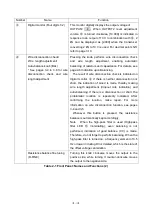
⑤
KeyLock switch
(KEY LOCK
)
On/Off switching for keyLock can be made by pressing
this knob for one second or longer. While in the lock
state, keyLock LED
⑥
illuminates. In this state, BAL
④
, measuring range selection
⑧
, measuring range fine
tuning
⑨
, calibration value setting
⑫
and filter setting
⑯
cannot be used. Pressing this knob for one second or
longer cancels the lock; keyLock LED
⑥
also comes
off.
⑥
KeyLock LED
This LED indicates whether keyLock is effective or not,
in that light-up for lock and light-out for unlock..
⑦
Bridge power voltage LED
(BV (V))
This LED indicates the bridge power voltage (2 V, 3 V, 5
V, 9V or 10 V). To select, use bridge power voltage
selection switch 2 on the rear panel. For more
details, see 2-11 Bridge Power Selection.
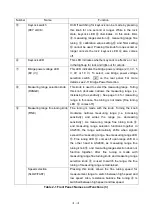
⑧
Measuring range selection knob
(RANGE)
This knob is used to select the measuring range. Turing
this knob clockwise narrows the measuring range (i.e.
increasing the sensitivity). See page 3-4 for measuring
range. In this case, fine tuning is not made. [Fine tuning
LED
⑩
comes off.]
⑨
Measuring range fine tuning knob
(FINE)
Fine tuning is made with the knob. Turning the knob
clockwise narrows measuring range (i.e. increasing
sensitivity) and wides the range (i.e. decreasing
sensitivity). As measuring range fine tuning knob
⑨
and measuring range selection functions together in
AS2503, the range automatically shifts when signals
exceed the measuring range. See measuring range LED
⑪
. Fine tuning LED
⑩
comes off upon range shift. On
the other hand in AS2603, as measuring range fine
tuning knob
⑨
and measuring range selection does not
function together. After fine tuning is made with
measuring range fine turning knob and measuring range
selection knob
⑧
is used to switch the range, the fine
tuning of measuring range is maintained.
Speed selection
(SLOW/FAST)
Pressing this knob allows the fine tuning speed for
measurement range to switch between high speed and
low speed. Also, resistance balance fine tuning
④
is
switched between high speed and low speed.
Table 2-1 Front Panel: Names and Functions (3)
Summary of Contents for AS2503
Page 1: ...AS2503 AS2603 DC BRIDGE SYSTEM DYNAMIC STRAIN AMPLIFIERS INSTRUCTION MANUAL 1WMPD4003356 ...
Page 2: ......
Page 4: ......
Page 30: ......
Page 46: ......
Page 68: ......
Page 83: ...9 5 9 3 External Dimensions 9 3 1 Amplifier Unit AS2503 ...
Page 84: ...9 6 9 3 2 Amplifier Unit AS2603 ...
Page 85: ...9 7 9 3 3 Panel Cut Sizes ...
Page 87: ...9 9 9 3 5 Rack mount Case Rack Rail Elongate Hole ...

