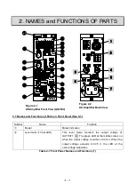
2-2
Number
Name
Function
③
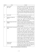
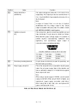
Digital monitor (Four digits 1/2)
This monitor digitally displays the output voltage of
OUTPUT2 4 . When OUTPUT2 level adjustment
volume
⑱
is turned clockwise, [10.000] is indicated in
response to an output of 10 V. In combination with
⑱
, 2
kN can be displayed as [2.000] when the transducer
converting 2 kN to 10 V is used. For decimal point shift,
refer to page 3-10.
④
Wire disconnection check/
Wire
length adjustment/
Auto-balance knob (BAL)
* See pages 3-4 to 3-6 for wire
disconnection check and wire
length adjustment
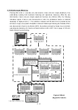
Pressing the knob performs wire disconnection check
and wire length adjustment, enabling automatic
balancing of resistors and capacitance. For details, see
page 2-6 Indication upon Balancing.
The result of wire disconnection check is indicated on
digital monitor
③
. If there is neither disconnection nor
short, the indication of Good is made, thereby making
wire length adjustment (dropout rate indication) and
auto-balancing. If there is a disconnection or short, the
problematic location is repeatedly indicated. After
confirming the location, make repair. For more
information on wire disconnection function, see pages
3-4 and 3-5.
Whenever this button is pressed, the resistance
balance is automatically kept accordingly.
Note When the high-pass filter is used (High-pass
filter LED
⑮
illuminating), even balancing is not
performed, indication of good balance (0 V) is made.
Therefore, do not forget to perform balancing. When the
high-pass filter is turned on, a frequency element of 0.5
Hz or lower including DC is deleted, which is the state of
the offset voltage cancellation.
Resistance balance fine tuning
(R-FINE)
Turning this knob clockwise moves the output to the
positive side, while turning it counter-clockwise moves
the output to the negative side.
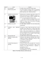
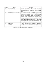
Table 2-1 Front Panel: Names and Functions (2)
Summary of Contents for AS2503
Page 1: ...AS2503 AS2603 DC BRIDGE SYSTEM DYNAMIC STRAIN AMPLIFIERS INSTRUCTION MANUAL 1WMPD4003356 ...
Page 2: ......
Page 4: ......
Page 30: ......
Page 46: ......
Page 68: ......
Page 83: ...9 5 9 3 External Dimensions 9 3 1 Amplifier Unit AS2503 ...
Page 84: ...9 6 9 3 2 Amplifier Unit AS2603 ...
Page 85: ...9 7 9 3 3 Panel Cut Sizes ...
Page 87: ...9 9 9 3 5 Rack mount Case Rack Rail Elongate Hole ...

