4-17
4.5 Special Applications
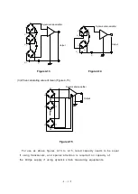
This section introduces examples that configure two or more bridges using a single power
supply and calculate value of addition, average, and subtraction using several transducers.
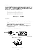
4.5.1 Configuring two or more bridges using a single power supply
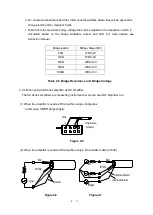
Figure 4-12
Connect the E terminal of each bridge box. If the power is supplied separately, connect either
of the power to the E terminal of the bridge box. The power supply should not exceed the
common mode voltage (
5V).
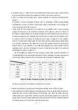
4. 5. 2 Special use of transducer
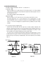
(1) When calculating value of addition (Figure 4-13)
Separate power supply is needed for E1, E2 and E3. In this case, 50 Hz or 60 Hz noise from
commercial power supply will affect the measurement. To minimize the influence of the noise,
add a capacitor.
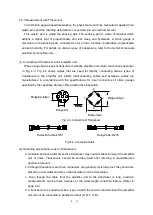
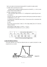
(2) When calculating value of subtraction (Figure 4-14)
Separate power supply is needed for E1 and E2. Also, in this case, 50 Hz or 60 Hz noise from
commercial power supply will affect the measurement. To minimize the influence of the noise,
add a capacitor.
D
D
B
B
B
C
C
E
E
E
C
A
A
A
Power supply
Output
Output
Dynamic strain amplifier
Output
D
Summary of Contents for AS2503
Page 1: ...AS2503 AS2603 DC BRIDGE SYSTEM DYNAMIC STRAIN AMPLIFIERS INSTRUCTION MANUAL 1WMPD4003356 ...
Page 2: ......
Page 4: ......
Page 30: ......
Page 46: ......
Page 68: ......
Page 83: ...9 5 9 3 External Dimensions 9 3 1 Amplifier Unit AS2503 ...
Page 84: ...9 6 9 3 2 Amplifier Unit AS2603 ...
Page 85: ...9 7 9 3 3 Panel Cut Sizes ...
Page 87: ...9 9 9 3 5 Rack mount Case Rack Rail Elongate Hole ...


