3-6
3.3 Wire Disconnection Check Function
3.3.1 Overview
The wire disconnection check function of the AS amplifiers can detect a bridge wire
disconnection, short, or cable disconnection. Since disconnected portions can easily be found,
testing personnel can reduce the measurement preparation time or prepare countermeasures
against wire disconnections. The wire disconnection check function can be set to on or off using the
dip switch on the bottom face of the AS amplifier.
(The bridge resistance should be 120
or higher.)
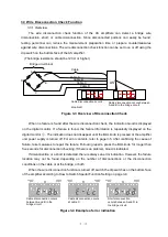
Figure 3-3 Overview of Disconnection Check
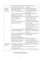
When no failure is found after the wire disconnection check, the indication Good is displayed
on the digital monitor. If a failure is found, the failure information is repeatedly displayed on the
digital monitor
③
. The indication does not disappear until the BAL knob is pressed or the amplifier
unit power supply is turned off. For error contents, refer to page 3-5. After confirming the cause of
failure, take measures to repair the failure. Following repairs, press the BAL knob for longer than
five seconds for disconnection checking. If there is no problem, Good is indicated.
If disconnection or a short is detected, there is always an error indication. However, the failure
location may not be found depending on the number of disconnections or the disconnection
conditions on the cable or at the bridge, or both.
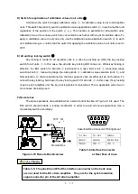
When the wire disconnection function is turned off, switch the dip switches on the bottom face
of the amplifier according to How to Switch Special Function Setting on page 3-9.
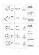
Figure 3-4 Example of error indication
Cable disconnection occurs between
A and B in the bridge circuit
.
Bridge circuit block
Cable
AS
A
B
C
D
Cable A
Cable disconnection occurs
at cable D
A
B
C
D
Cable B
Cable C
Cable D
Cable disconnection occurs
at cable C
Cable disconnection occurs
between A and B in the
bridge circuit
.
Short disconnection
occurs between A and D in
the bridge circuit
.
Summary of Contents for AS2503
Page 1: ...AS2503 AS2603 DC BRIDGE SYSTEM DYNAMIC STRAIN AMPLIFIERS INSTRUCTION MANUAL 1WMPD4003356 ...
Page 2: ......
Page 4: ......
Page 30: ......
Page 46: ......
Page 68: ......
Page 83: ...9 5 9 3 External Dimensions 9 3 1 Amplifier Unit AS2503 ...
Page 84: ...9 6 9 3 2 Amplifier Unit AS2603 ...
Page 85: ...9 7 9 3 3 Panel Cut Sizes ...
Page 87: ...9 9 9 3 5 Rack mount Case Rack Rail Elongate Hole ...

