4-13
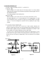
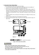
Care must be taken concerning the following points for connection to a data recorder.
(1) Where direct connections can be made
If a data recorder is capable of accepting a signal of more than 20 V
p
-
p
(+/-10V), it can be
directly connected to the amplifier unit.
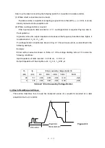
(2) Where a voltage divider is required
If the input level of a data recorder is +/-1 V, a voltage divider is required. Pay due care to
the impedance.
In general, since the output impedance increases as the frequency band becomes higher, it
is expressed as:
R
0
(
)
+
L
0
(
H
)
.
If a voltage divider is inserted as shown in Fig. 4.7, this will cause errors, as described in the
following example.
Example:
Errors will be caused as shown in Table 4.7, if the voltage dividing ratio is 1/10 under the
following conditions:
Input impedance of data recorder:
Ri
=100
k
,
Ci
=100
pF
Output impedance of the amplifier unit:
R
0
=
1
,
L
0
=200
H
R
1
(kΩ)
R
2
(kΩ)
Errors caused by voltage divider (5)
DC
1kHz
2kHz
5kHz
10kHz
90
11.1
-0.08
-0.08
-0.09
-0.12
-0.24
9
1.01
-0.02
0.02
-0.02
-0.02
-0.02
Table 4-7 Error Caused by Voltage Divider
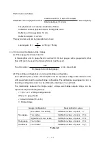
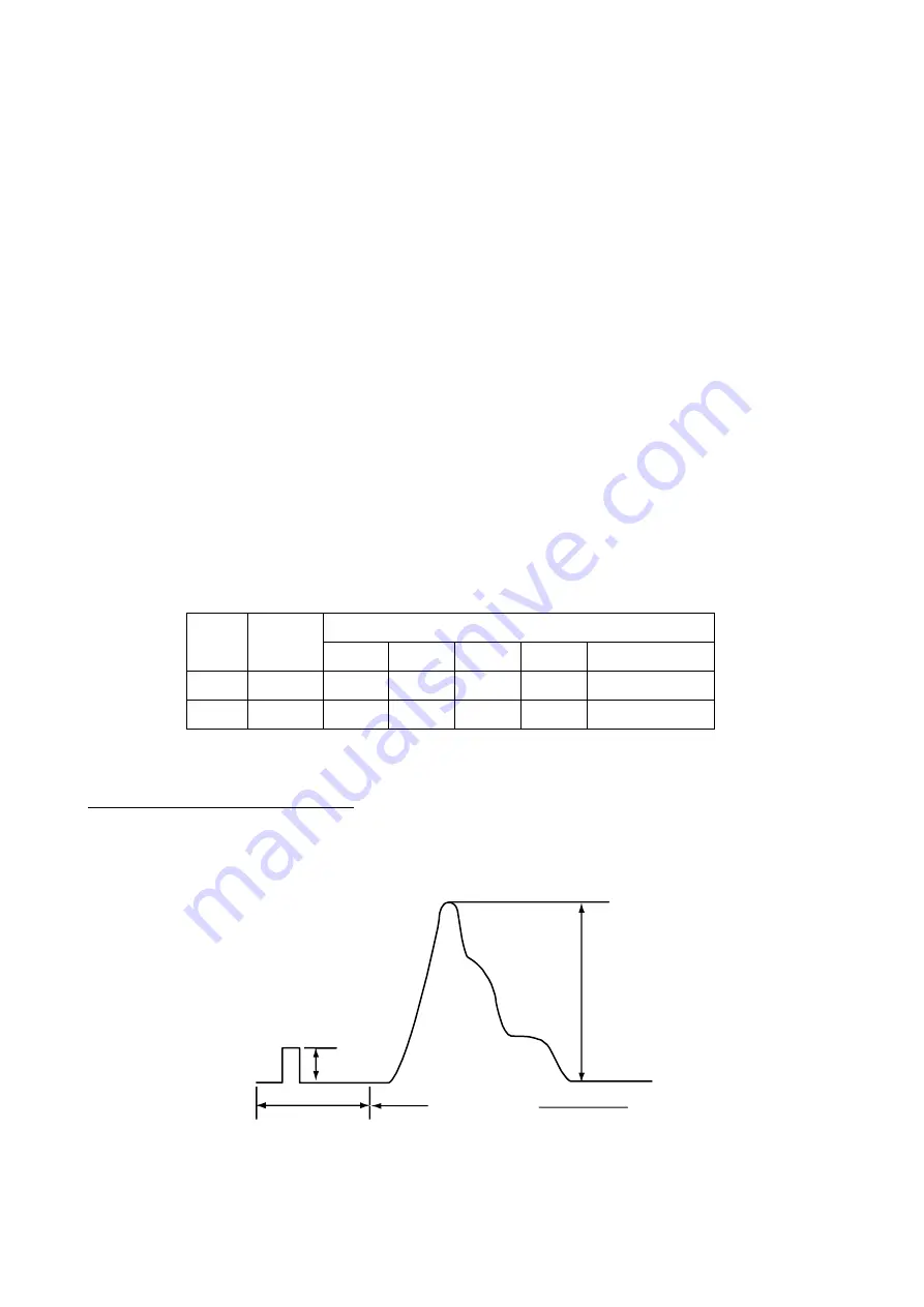
4.4 How to Read Measured Values
This section describes how to read the measured values of a waveform recorded on a data
acquisition device or recorder.
Figure 4-10
CAL value
a
A
B
b
Waveform
Measurement
Summary of Contents for AS2503
Page 1: ...AS2503 AS2603 DC BRIDGE SYSTEM DYNAMIC STRAIN AMPLIFIERS INSTRUCTION MANUAL 1WMPD4003356 ...
Page 2: ......
Page 4: ......
Page 30: ......
Page 46: ......
Page 68: ......
Page 83: ...9 5 9 3 External Dimensions 9 3 1 Amplifier Unit AS2503 ...
Page 84: ...9 6 9 3 2 Amplifier Unit AS2603 ...
Page 85: ...9 7 9 3 3 Panel Cut Sizes ...
Page 87: ...9 9 9 3 5 Rack mount Case Rack Rail Elongate Hole ...

