2-7
2.3 How to Set Calibration Value (CAL) (Entering voltage)
To change the unit from mV to µ
and µ
to mV, depress calibration value setting knob
⑫
(See
Figure 2-5) for one second or longer. Then, the indication of LED changes (e.g., fromµ
to mV). You
can change the unit by depressing the calibration value setting knob
⑫
for one second or longer
when setting the value of each digit. The settable values are as follows.
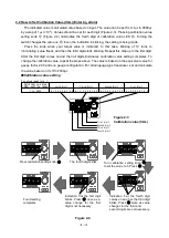
■
Calibration value setting
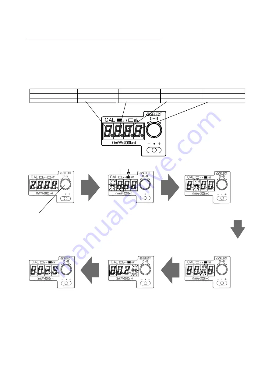
E.g. When changing the CAL value from 2000µ
to 80.25 mV (See Figure 2-6)
Forth Digit
Third Digit
Second Digit
First Digit
0.01~9.99
0
0.1.2.3.4.5.6.7.8.9.
0 1 2 3 4 5 6 7 8 9
0 1 2 3 4 5 6 7 8 9
1 2 3 4 5 6 7 8 9
0.1.2.3.4.5.6.7.8.9.
0 1 2 3 4 5 6 7 8 9
0 1 2 3 4 5 6 7 8 9
10.00~99.99
CAL
For voltage input (mV)
Figure 2-6
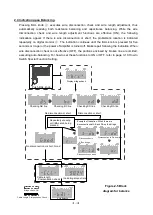
As soon as the fourth digit blinks,
decimal number digit starts blinking.
The unit of LED ⑬ changes from
µ
to mV. Turn ⑫ and set the value
to 8, and then press ⑫.
A value of 2 is illuminated on the
second digit, and then the first digit
blinks. Turn
⑫
to set to 5, and
after that Press
⑫
.
All digits illuminates,
and the setting is completed
after 80.05 is indicated.
A value of 8 is illuminated on
the forth digit and also the
third digit blinks. As the third
digit value cannot changed
(staying to be 0), press
⑫
.
A value of 0 is illuminated on the
third digit, and then the second
digit blinks. Turn
⑫
to set 2,
and after that press
⑫
.
Press calibration value setting
knob
⑫
for one second or
longer.
Figure 2-5
Summary of Contents for AS2503
Page 1: ...AS2503 AS2603 DC BRIDGE SYSTEM DYNAMIC STRAIN AMPLIFIERS INSTRUCTION MANUAL 1WMPD4003356 ...
Page 2: ......
Page 4: ......
Page 30: ......
Page 46: ......
Page 68: ......
Page 83: ...9 5 9 3 External Dimensions 9 3 1 Amplifier Unit AS2503 ...
Page 84: ...9 6 9 3 2 Amplifier Unit AS2603 ...
Page 85: ...9 7 9 3 3 Panel Cut Sizes ...
Page 87: ...9 9 9 3 5 Rack mount Case Rack Rail Elongate Hole ...

