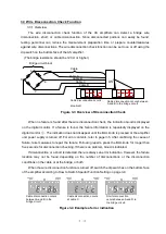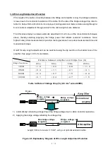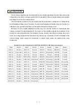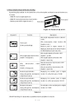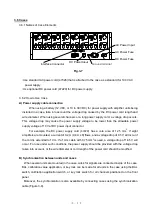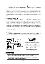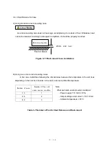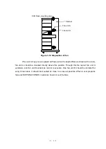
4-2
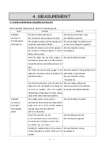
The housing case must be properly grounded
(when the system operates on AC power).
Prevents noise from entering
the equipment.
Operation of
dynamic strain
amplifier system.
Select the bridge supply voltage in accordance
with the strain gauge to be used.
Prevents measurement errors due
to generation of heat in strain gauges.
The connectors must be properly connected.
Prevents instability in operation and
poor connections.
Care must be taken not to smear the input
connector with oil, dirt, or anything else.
Prevents instability in operation and
poor connections.
Verify that the power supply voltage is within
the range of specifications.
AC: 85
– 132 V, or 198 – 264 V
DC: 10
– 30 V
Check that the polarity of the battery is correct,
especially when 12 VDC is used.
If the supply voltage is less than the lower
limit, failures in operation may occur.
If the supply voltage is higher than
the specified upper limit, heat may be
produced, which may result in damaging
electronic components.
If the polarity of the battery is not correct, the
amplifier system will not operate.
(However, the system and the battery will
not be damaged though.)
Do not apply pressure to strain gauges when
units are in the auto balancing mode.
Applying pressure to strain gauges in auto
balancing mode causes the bridge to be
unbalanced.
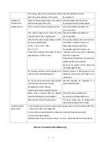
Do not turn the measurement range selector
control
⑧
or the measurement range
fine adjustment control
⑨
during
measurement. (Use the keylock function.)
Prevents changing the amplitude of a
preset calibration value.
Before using a low-pass filter, the operator
should be familiar with its characteristics.
Prevents reducing amplitude and
the occurrence of phase differences.
Prevent short-circuit in the output cable.
The power supply may be disabled, and
heat will be generated in the circuitry.
Countermeasures
against noise
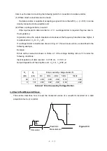
1. Use shielded wires as leads connecting strain gauges and connect the metal shields of the
wires to terminal E on the bridge box.
2. Connect the ground terminal of the bridge box to terminal E and the base metal.
3. Ground the output common.
Performing all of or any of the above steps, 1, 2, and 3, may be effective for noise reduction.
Table 4-1 Causations before Measuring
Summary of Contents for AS2503
Page 1: ...AS2503 AS2603 DC BRIDGE SYSTEM DYNAMIC STRAIN AMPLIFIERS INSTRUCTION MANUAL 1WMPD4003356 ...
Page 2: ......
Page 4: ......
Page 30: ......
Page 46: ......
Page 68: ......
Page 83: ...9 5 9 3 External Dimensions 9 3 1 Amplifier Unit AS2503 ...
Page 84: ...9 6 9 3 2 Amplifier Unit AS2603 ...
Page 85: ...9 7 9 3 3 Panel Cut Sizes ...
Page 87: ...9 9 9 3 5 Rack mount Case Rack Rail Elongate Hole ...


