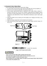
4-12
4.3 Connection of Output to Load
Two types of outputs are available;
OUTPUT 1 and OUTPUT 2.
(1) OUTPUT 1
3
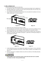
Delivers a voltage of +/-10 V and a current of +/-5 mA (into a load of 2
k
or more), allowing
voltage-input type instruments such as thermal dot recorders and data acquisition devices to
be connected to OUTPUT 1.
Thus output is displayed on the monitoring meter .
(2)OUTPUT 2
4
Delivers a voltage of +/-10 V and a current of +/-10 mA (into a load of 332
or more).
The output voltage of O
UTPUT2
can be varied from +/-10 V to approxi/-1 V with
the level adjustment control
⑱
. Because this output can be displayed digitally on the digital
monitor
③
, it can also be displayed as a physical amount by adjusting the output voltage
(scaling).
4.3.1 Connection of Output to Data Recorder
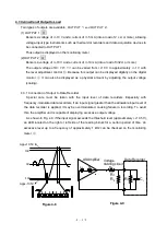
Special care must be taken with the input level of data recorders. Especially with
frequency-modulated data recorders, if an input signal greater than the allowable input level of
the data recorder is applied, it may be overmodulated, causing failure in recording. To avoid
this, the amplifier unit is capable of displaying excessive output voltage.
As shown in Fig. 4.8, if the input signal exceeds the threshold level (approxi/-10.5 V),
an LED located on the right or left side of the reading blinks for a certain period of time. An
excessive level up to a frequency of approximately 1 kHz can be checked on the monitoring
meter
②
.
Data Recorder
L
0
Voltage
dividing circuit
AS Amplifier
R
1
R
2
Ri
C
i
Figure 4-9
R
0
R
0
Appx.10.5V
Figure 4-8
10V
0V
-10V
Appx.-10.5V
Summary of Contents for AS2503
Page 1: ...AS2503 AS2603 DC BRIDGE SYSTEM DYNAMIC STRAIN AMPLIFIERS INSTRUCTION MANUAL 1WMPD4003356 ...
Page 2: ......
Page 4: ......
Page 30: ......
Page 46: ......
Page 68: ......
Page 83: ...9 5 9 3 External Dimensions 9 3 1 Amplifier Unit AS2503 ...
Page 84: ...9 6 9 3 2 Amplifier Unit AS2603 ...
Page 85: ...9 7 9 3 3 Panel Cut Sizes ...
Page 87: ...9 9 9 3 5 Rack mount Case Rack Rail Elongate Hole ...

