8-2
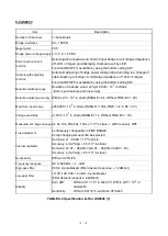
Item
Explanation
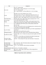
Noise level
80 × 10
-6
in strain p-p RTI
(W/B, RANGE = 1k
, Without FINE, BV = 2V, 120 Ω in bridge)
20 × 10
-6
in strain p-p RTI
(DC
– 30kHz, RANGE = 1k, Without FINE, BV = 2V, 120 Ω in bridge)
Output
OUTPUT1 ±10 V ±5 mA, OUTPUT2 ±10 V ±10m A
Output impedance: 0.5Ω or less, Capacitive load: Operable up to 0.1 μF
(For output current of 4 -
20mA: Load impedance: 500 Ω or less, Output
impedance: Approx. 5 MΩ, Voltage/current conversion accuracy: Within ±0.1%)
Output adjustment
OUTPUT2 ADJ (Can be independently varied continuously from 1 to 1/10)
Output monitor
display
17-dot LED display (OUTPUT1 monitor)
Green LED at center blinks when voltage is within approximately ±100 mV.
LEDs at both ends blink when voltage is greater than approximately ±10.5 V.
Digital display
4 1/2 digital display (OUTPUT2 monitor), Scaling display available with
OUTPUT2 ADJ
Accuracy: Within ±0.05% rdg ±1 count, Displaying location of decimal point can
be changed by using the bottom setting SW.
Key lock function
Turning the key lock ON/OFF by pressing the key lock button approximately for
one second.
(Except CAL switch and BV selection switch)
Setting value saving
Saving the value in flash memory. (Can be held without back-up battery)
Resistance to vibration
29.4m/s
2
(50Hz, X,Y,Z, 10 minutes for each) and conforming to MIL-STD-810F
514.5C-1
Withstand Voltage
(Insulation resistance)
1.5 kVAC, 1 minute, between each input terminal output and housing case
1 kVAC, 1 minute, between DC power input and input
500 VAC, 1 minute, between DC power input and output or housing case
AC power supply
85 - 132 VAC/180 - 264 VAC (Internal switch must be changed) 10 VA or less
DC power supply
DC10 - 30V, 7 VA or less
Operating environmental
conditions
- 10°C - + 50°C, Within 20 - 85% RH, without condensation
Storage temperature range - 20°C to + 70°C, Within 10 - 90% RH
Outline dimension
H143 (±1.0) × W49.5 (±0.5) × D253 (±2.0) mm *Excluding protrusion
Weight
Within 1.4 (±0.1) kg
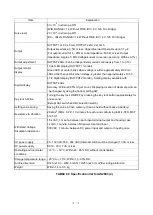
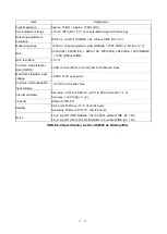
TABLE 8-1 Specification list for AS2503 (2)
Summary of Contents for AS2503
Page 1: ...AS2503 AS2603 DC BRIDGE SYSTEM DYNAMIC STRAIN AMPLIFIERS INSTRUCTION MANUAL 1WMPD4003356 ...
Page 2: ......
Page 4: ......
Page 30: ......
Page 46: ......
Page 68: ......
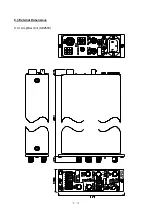
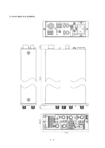
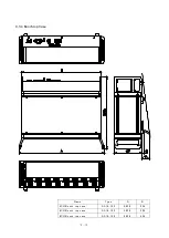
Page 83: ...9 5 9 3 External Dimensions 9 3 1 Amplifier Unit AS2503 ...
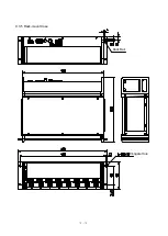
Page 84: ...9 6 9 3 2 Amplifier Unit AS2603 ...
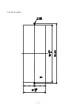
Page 85: ...9 7 9 3 3 Panel Cut Sizes ...
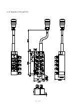
Page 87: ...9 9 9 3 5 Rack mount Case Rack Rail Elongate Hole ...

