


98
A2A
SIMULATIONS :::
ACCU-SIM V35B BONANZA
SYSTEMS DESCRIPTION
FOR SIMULATION USE ONLY
ENVIRONMENTAL SYSTEMS
CABIN HEATING
A heater muffler on the right exhaust stack provides for
heated air to five outlets in the forward and aft areas of the
cabin. The two forward outlets are located above and forward
of each set of rudder pedals. The two aft outlets are installed
behind the right front seat and the right rear seat. The fifth
outlet provides heated air for windshield defrosting.
In flight, ram air enters an intake on the right side of the
nose, passes through the heater muffler, then into a mixer
valve on the forward side of the firewall. In the mixer valve,
the heated air is combined with a controlled quantity of
unheated ram air picked up at an intake at the rear engine
baffle. Air of the desired temperature is then ducted from
the mixer valve to the outlets in the cabin.
HEATER AND DEFROSTER OPERATION
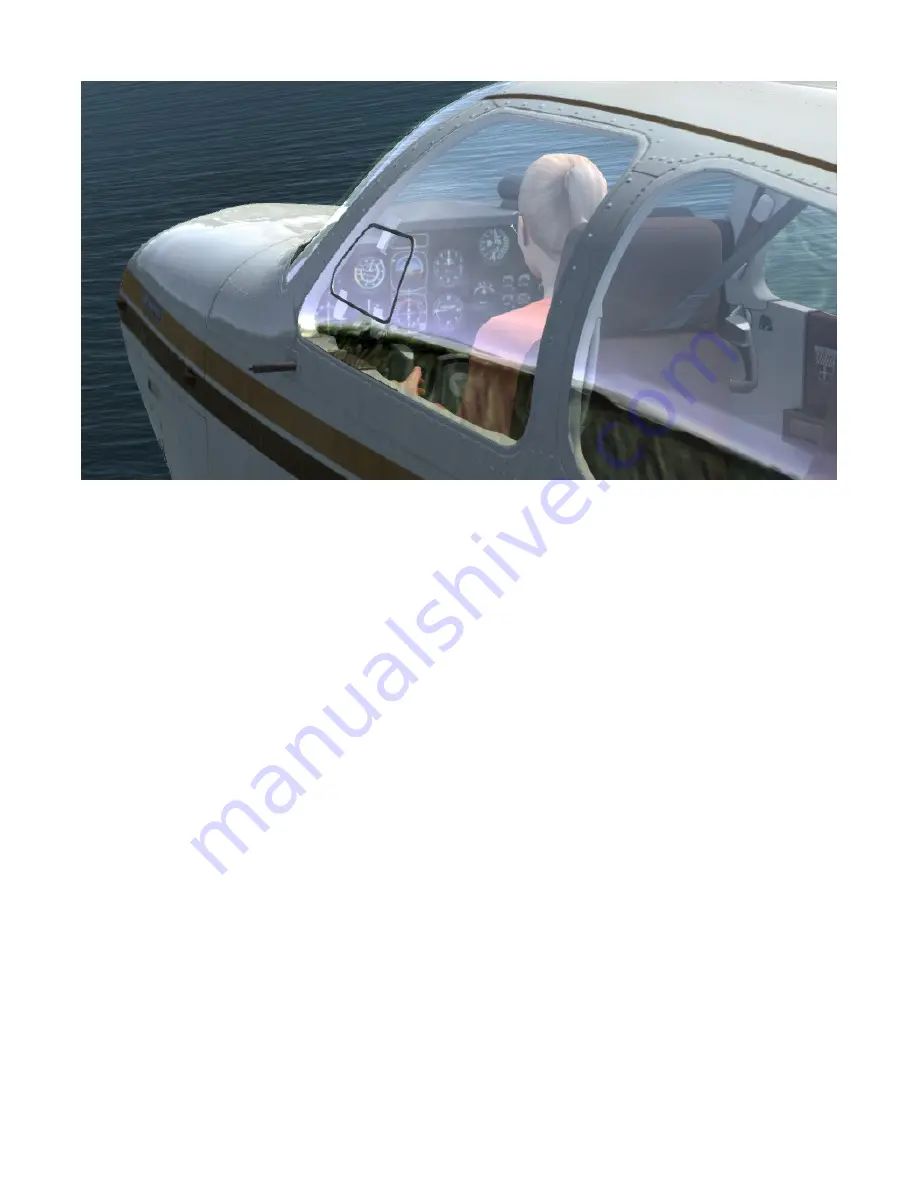
The heater controls are located on the lower left pilot’s sub-
panel. To obtain heated air to the cabin outlets, pull the
CABIN HEAT control. The control regulates the amount of
cold air that is mixed with the air from the heater muff.
When the control is pulled fully out, the cold air is shut off
and only heated air enters the cabin. The forward vents,
located on the firewall forward of the rudder pedals, deliver
heated air to the forward cabin when the CABIN HEAT con-
trol is pulled out. To deliver heated air to the aft seat outlets
pull the AFT CABIN HEAT control. For maximum heat, the
control is pulled fully out. To obtain heated air for defrost-
ing the windshield pull the DEFROST control out. It may be
necessary to vary or close the AFT CABIN HEAT control to
obtain maximum air flow for defrosting. To close off all air
from the heater system, pull the red FIREWALL AIR control
located to the extreme left of the pilot’s lower subpanel.
CABIN VENTILATION
In moderate temperatures, ventilation air can be obtained
from the same outlets used for heating, by pushing the
CABIN HEAT control full forward. However, in extremely
high temperatures, it may be desirable to pull the red
FIREWALL AIR control and use only the fresh air outlets
described in the following paragraphs.
CABIN FRESH AIR OUTLETS
A duct in each wing root is connected directly to an adjust-
able outlet in the upholstery panel forward of each front
seat. Airflow from each outlet is controlled by a center knob.
The direction of airflow is controlled by rotating the lou-
vered cover with the small knob on the rim.
OPTIONAL FRESH AIR VENT BLOWER
An optional fresh air vent blower controlled by an ON-OFF
switch on the subpanel is available on serials D-10348, D-
10364 and after. It provides ventilation through the indi-
vidual overhead outlets during both ground and in-flight
operations.
INDIVIDUAL OVERHEAD FRESH AIR OUTLETS
Fresh ram air from the air intake on the upper side of the aft
fuselage is ducted to individual outlets above each seat. Each
outlet can be positioned to direct the flow of air as desired.
The volume of incoming air can be regulated by rotating
the outlet. A system shutoff valve is installed in the duct
Summary of Contents for BONANZA ACCU-SIM V35B
Page 1: ...A2ASIMULATIONS BONANZA ACCU SIM V35B BONANZA ...
Page 3: ...A2ASIMULATIONS BONANZA ACCU SIM V35B BONANZA ...
Page 5: ...www a2asimulations com ACCU SIM V35B BONANZA A2ASIMULATIONS 5 FOR SIMULATION USE ONLY ...
Page 27: ...www a2asimulations com ACCU SIM V35B BONANZA A2ASIMULATIONS 27 FOR SIMULATION USE ONLY ...
Page 58: ......
Page 68: ...68 A2ASIMULATIONS ACCU SIM V35B BONANZA www a2asimulations com FOR SIMULATION USE ONLY ...
Page 112: ......


