


96
A2A
SIMULATIONS :::
ACCU-SIM V35B BONANZA
SYSTEMS DESCRIPTION
FOR SIMULATION USE ONLY
is being supplied to the starter. If the light remains illumi-
nated after starting, the starter relay has remained engaged
and loss of electrical power may result. The battery and
alternator switches should be turned off if the light remains
illuminated after starting. If the light does not illuminate
during starting, the indicator system is inoperative and the
ammeter should be monitored to ensure that the starter
does not remain energized after starting. The starter ener-
gized warning light can be tested with the TEST-BAT-DIM-
WARN LIGHTS switch adjacent to the warning lights on the
floating instrument panel.
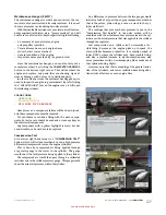
PROPELLER
Installed as standard equipment on the Bonanza is a con-
stant speed, variable pitch, 84”-diameter propeller with
two aluminum alloy blades. The pitch setting at the 30-inch
station is 13.3° low and 29.2° high pitch.
Propeller rpm is controlled by a governor which regulates
hydraulic oil pressure to the hub. A push-pull knob on the
control console allows the pilot to select the governor’s rpm
range.
If oil pressure is lost, the propeller will go to the full high
rpm position. This is because propeller low rpm is obtained
by governor boosted engine oil pressure working against the
centrifugal twisting moment of the blades.
FUEL SYSTEM
The airplane is designed for operation on 100/130 grade
(green) aviation gasoline. However, the use of 1 00LL (blue)
is preferred.
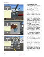
FUEL CELLS
The 74-gallon usable (80-gallon capacity) system only is
available on D-10303 and after. The fuel system consists of
a rubber fuel cell in each wing leading edge with a flush
type filler cap. A visual measuring tab
is attached to the filler neck of the
optional system. The bottom of the
tab indicates 27 gallons of usable fuel
and the detent on the tab indicates
32 gallons of usable fuel in the tank.
The engine driven fuel injector pump
delivers approximately 1 0 gallons of
excess fuel per hour, which bypasses
the fuel control and returns to the
tank being used. Three fuel drains are
provided, one in each fuel sump on
the underside of each wing and one in
the fuel selector valve inboard of the
left wing root. These points should be
drained daily before the first flight.
An additional 40 gallons of fuel and
200lbs of gross weight capacity can be
added when tip tanks are installed.
FUEL QUANTITY
INDICATION SYSTEM
Fuel quantity is measured by float operated sensors, located
in each wing tank system. These transmit electrical signals
to the individual indicators, which indicate fuel remaining
in the tank. There are sensors in each wing tank system
connected to the individual wing tank indicator.
AUXILIARY FUEL PUMP
The electric auxiliary fuel pump is controlled by an ON-OFF
toggle switch on the control console and provides pres-
sure for starting and emergency operation. Immediately
after starting, the auxiliary fuel pump can be used to purge
the system of vapor caused by an extremely high ambient
temperature or a start with the engine hot. The auxiliary
fuel pump provides for near maximum engine fuel require-
ments, should the engine driven pump fail.
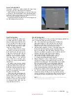
FUEL TANK SELECTION
The fuel selector valve handle is located forward and to
the left of the pilot’s seat. Takeoffs and landings should be
made using the tank that is more nearly full.
On airplanes D-10404 and after, the pilot is cautioned to
observe that the short, pointed end of the handle aligns with
the fuel tank position being selected. The tank positions
are located on the aft side of the valve. The OFF position
is forward and to the left. An OFF position lock-out fea-
ture has been added to prevent inadvertent selection of the
OFF position. To select OFF, depress the lock-out stop and
rotate the handle to the full clockwise position. Depression
of the lock-out stop is not required when moving the handle
counterclockwise from OFF to LEFT MAIN or RIGHT MAIN.
When selecting the LEFT MAIN or RIGHT MAIN fuel tanks,
position handle by sight and feeling for detent.
If the engine stops because of insufficient fuel, refer to
the EMERGENCY PROCEDURES Section for the Air Start
procedures.
Summary of Contents for BONANZA ACCU-SIM V35B
Page 1: ...A2ASIMULATIONS BONANZA ACCU SIM V35B BONANZA ...
Page 3: ...A2ASIMULATIONS BONANZA ACCU SIM V35B BONANZA ...
Page 5: ...www a2asimulations com ACCU SIM V35B BONANZA A2ASIMULATIONS 5 FOR SIMULATION USE ONLY ...
Page 27: ...www a2asimulations com ACCU SIM V35B BONANZA A2ASIMULATIONS 27 FOR SIMULATION USE ONLY ...
Page 58: ......
Page 68: ...68 A2ASIMULATIONS ACCU SIM V35B BONANZA www a2asimulations com FOR SIMULATION USE ONLY ...
Page 112: ......


