E3
TERMINAL BLOCK CONNECTIONS
Earth
N
Neutral
L
Live input of the controller
L
3
Live input for the solar heating system modulating pump
PWM+ PWM+ stuursignaal t.b.v. aansturing pomp zonnesysteem
PWM- PWM- stuursignaal t.b.v. aansturing pomp zonnesysteem
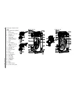
COMPONENTS
AA
Controller
BB
[VAC]
Solar heating system pump (modulating) (230 VAC)
BB
[PWM]
Solar heating system pump (modulating) (PWM-signal)
CC
Temperature sensor (S
1
- solar collector)
DD
Temperature sensor (S
2
- tank)
EE
Combined Q/T sensor
(incl. temperature sensor S
4
- solar collector return)
FF
Communication between the water heater controller and the solar
Heating system controller (BUS-link)
GG
Temperature sensor (S
3
- top of storage tank)
K
Double-pole isolator
CONTROLLER CONNECTIONS
J12
Connection of combined Q/T sensor (1-2-3-4)
J13
Connection of temperature sensor S
1
(2-4)
J14
Connection of temperature sensor S
2
(2-4) and temperature sensor S
3
(1-3)
J16
Connection of BUS-link communication
J18
Connection of PWM-signal solar heating system pump
F2
Fuse (T 3.15A - 250 V)
Summary of Contents for SGS - 100
Page 7: ...4 Instruction manual SGS gis...
Page 11: ...Contents 8 Instruction manual SGS...
Page 23: ...Working principle of the water heater 20 Instruction manual SGS 2 gis...
Page 37: ...Installation types 34 Instruction manual SGS Installation 3...
Page 57: ...Conversion to a different gas category 54 Instruction manual SGS 4 is...
Page 65: ...Draining 62 Instruction manual SGS 6 gis...
Page 71: ...Status of the water heater 68 Instruction manual SGS 8 gis...
Page 75: ...Shutting down 72 Instruction manual SGS 10 gis...
Page 103: ...Service interval 100 Instruction manual SGS 14 is...
Page 112: ...Instruction manual SGS 109 is...
Page 119: ...Instruction manual SGS 116...


