Instruction manual SGS
37
is
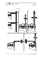
Concentric roof flue terminal specifications C33
3.10.4
Parallel connections
The table states the maximum pipe lengths for parallel systems. The maximum
pipe length depends on the chosen diameter.
Warning
Install flue gas discharge pipe runs with a run-off of 5 mm per metre towards
the water heater.
Chimney flue requirements for parallel systems
You must use the longest pipe when calculating the pipe length. For example, if
the chimney pipe is 10 metres and the air supply pipe is 8 metres, use 10 metres
as the length for the calculation. Next, add the L
equivalent
for
every
90° and 45°
bend to this 10 metres, in
both
the air supply and flue gas outlet. The following
practical example illustrates how to use the table.
Subject
Description
Roof conduit set:
•
1x roof conduit (incl. clamping
ring)
•
1x Pipe 1000 mm
•
1x adhesive sheet
Art. No.
SGS 28, 30, 50, 60
03
11 460
1
SGS 80, 100, 120
03
11 461
1
Manufacturer
Muelink & Grol
Type
Skyline
3000
(28-60) and
M
ugro
2000
(80-120)
Pipe material
Construction
Concentric
Flue gas discharge
Thick-walled aluminium with lipped sealing ring.
Air supply
Thin-walled galvanised sheet steel.
Pipe diameters
Flue gas discharge
SGS 28, 30, 50, 60
Ø 100 mm
SGS 80, 100, 120
Ø 130mm
Air supply
SGS 28, 30, 50, 60
Ø 150 mm
SGS 80, 100, 120
Ø 200 mm
(1)
No other roof flue terminal may be used. Use this item number to order the roof flue terminal set from the
supplier
, manufacturer or wholesalor.
Appliance
Diameter
1
Maximum
total
length
L
equivalent
90º bend
L
equivalent
45º bend
SGS 28, 30, 50, 60
100 mm
55 m
4.6 m
1.2 m
SGS 80, 100, 120
130 mm
65 m
2.4 m
1.4 m
SGS 28, 30, 50, 60
130 mm
100 m
2.4 m
1.4 m
SGS 80, 100, 120
150 mm
100 m
2.6 m
1.6 m
1) Parallel systems with diameter of 100 mm or 130 mm. If the maximum total
length when using a diameter of 130 mm is insufficient, a diameter of 150 mm
must be used. If the maximum total length when using a diameter of 130 mm
is insufficient, a diameter of 150 mm must be used. Any diameter enlargement
must be carried out on both air supply and flue gas outlet.
Summary of Contents for SGS - 100
Page 7: ...4 Instruction manual SGS gis...
Page 11: ...Contents 8 Instruction manual SGS...
Page 23: ...Working principle of the water heater 20 Instruction manual SGS 2 gis...
Page 37: ...Installation types 34 Instruction manual SGS Installation 3...
Page 57: ...Conversion to a different gas category 54 Instruction manual SGS 4 is...
Page 65: ...Draining 62 Instruction manual SGS 6 gis...
Page 71: ...Status of the water heater 68 Instruction manual SGS 8 gis...
Page 75: ...Shutting down 72 Instruction manual SGS 10 gis...
Page 103: ...Service interval 100 Instruction manual SGS 14 is...
Page 112: ...Instruction manual SGS 109 is...
Page 119: ...Instruction manual SGS 116...


