Working principle of the water heater
18
Instruction manual SGS
2
gis
2.5.1
Unvented installation
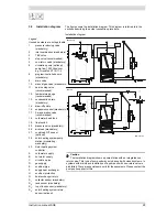
With an unvented installation, an expansion valve and expansion vessel prevent
the buildup of excessive pressure in the tank. This prevents damage being
caused to the enamel coating (in the water heater) or to the tank. A non-return
valve prevents excessive pressure build-up in the water supply system. This
valve also prevents water from flowing backwards from the tank into the cold
water supply system. The pressure-reducing valve protects the water heater
against excess mains water pressure (3.4.2 "General and electrical
specifications"). These components are installed in the cold water
inlet (3.7 "Vented water connections").
2.5.2
Vented installation
With a vented installation, excess pressure is taken up by the open cold water
head tank. The level of the cold water head tank determines the maximum
working pressure (3.4.2 "General and electrical specifications") in the tank. The
water heater must also be fitted with a vent pipe from the hot water pipe, which
opens into the cold water head tank.
Ideally, the vent pipe should discharge into a separate discharge channel/drain
or otherwise to the open cold water head tank. The water heater should also be
fitted with a stop valve (3.6.2 "Hot water side") on the hot water side.
2.5.3
T&P valve
A T&P (Temperature and Pressure Relief) valve monitors the pressure in the
tank and the water temperature at the top of the tank. If the pressure in the tank
becomes too high or the water temperature becomes too hot, the valve will
open. The hot water can now flow out of the tank. Because the water heater and
storage tank are under water supply pressure, cold water will automatically flow
into the tank. The valve remains open until the unsafe situation has been
rectified. The water heater and storage tank are fitted standard with a
connection for a T&P valve (3.6.2 "Hot water side").
2.6
Protection for the
solar heating system
2.6.1
Drain-back tank
The solar heating system may optionally be equipped with a drain-back tank.
The tank fills itself with the heating fluid when there is no heat demand. This
avoids overheating of the solar heating system. The high insulation factor of the
tank also protects the system against freezing of the fluid. The use of the drain-
back tank also serves to extend the useful life of the fluid.
The existence of a drain-back tank is set (12.9.1 "Setting the drain-back tank")
during the installation. Refer to the solar heating system manual for more
details.
2.6.2
Fluid temperature
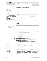
The heat exchanger of the solar heating system is filled with glycol. If the
temperature of the heating fluid is too high, a signal is sent to the controller of
the solar collector and the pump of the solar collector is switched off. This signal
is passed to the controller by temperature sensor S
1
.
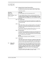
Temperature protection for solar heating system
Protection
Description
Maximum temperature:
- S
1
> 130°C
The pump of the solar heating system switches off
when the temperature of the heating fluid at S
1
exceeds the maximum value. The solar heating
system enters error mode. The error is also visible
on the display of the SGS water heater
Summary of Contents for SGS - 100
Page 7: ...4 Instruction manual SGS gis...
Page 11: ...Contents 8 Instruction manual SGS...
Page 23: ...Working principle of the water heater 20 Instruction manual SGS 2 gis...
Page 37: ...Installation types 34 Instruction manual SGS Installation 3...
Page 57: ...Conversion to a different gas category 54 Instruction manual SGS 4 is...
Page 65: ...Draining 62 Instruction manual SGS 6 gis...
Page 71: ...Status of the water heater 68 Instruction manual SGS 8 gis...
Page 75: ...Shutting down 72 Instruction manual SGS 10 gis...
Page 103: ...Service interval 100 Instruction manual SGS 14 is...
Page 112: ...Instruction manual SGS 109 is...
Page 119: ...Instruction manual SGS 116...


