


Installation
32
Instruction manual SGS
3
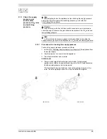
is
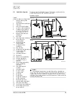
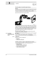
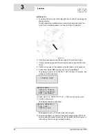
See (D) in the installation diagram (3.5 "Installation diagram").
1. Fit a manual gas valve (10) in the gas supply pipe.
2. Blow the gas pipe clean before use.
3. Close the manual gas valve.
4. Fit the gas supply pipe to the gas control valve.
Warning
After fitting, check for leaks.
3.9
Solar heating system
Note
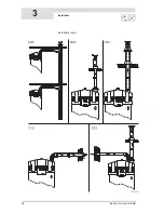
Please refer to the installation diagram (3.5 "Installation diagram"), electrical
diagram (17.4 "Electrical diagram, solar heating system") and terminal
block (3.12.1 "Preparation") for details of how to connect the solar heating
system.
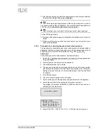
1. Connect the supply from the solar collector to the inlet (F) of the heat
exchanger.
2. Connect the return pipe to the solar collector to the outlet (G) of the heat
exchanger.
3. Connect the lead to the solar heating system controller and sensor S
2
, see:
-
electrical diagram (17.4 "Electrical diagram, solar heating system")
and
-
connections table (3.11.2 "Preparation").
4. Connect the communication cable between the solar heating system
controller and the water heater, see:
-
electrical diagram (17.4 "Electrical diagram, solar heating system")
and
-
connections table (3.11.2 "Preparation").
Warning
The installation diagram shows a pump station with an integrated non-return
valve. This type of pump unit may only be used with closed systems. In systems
with drain-back, installation of a pump unit with non-return valve is prohibited.
There are special pump units for these systems. Please contact the pump unit
supplier for this.
3.10 Air supply and
chimney flue
discharge
3.10.1
Introduction
This section covers the following topics:
•
Requirements for flue gas discharge materials
•
Concentric connections
•
Parallel connections
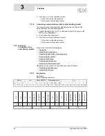
3.10.2
Requirements for flue gas discharge materials
Warning
The installation should be carried out by a competent person, in compliance
with general and locally applicable regulations (1.3 "Regulations").
Depending on the approved installation types, there are several alternatives for
connecting the air supply and chimney flue.
Summary of Contents for SGS - 100
Page 7: ...4 Instruction manual SGS gis...
Page 11: ...Contents 8 Instruction manual SGS...
Page 23: ...Working principle of the water heater 20 Instruction manual SGS 2 gis...
Page 37: ...Installation types 34 Instruction manual SGS Installation 3...
Page 57: ...Conversion to a different gas category 54 Instruction manual SGS 4 is...
Page 65: ...Draining 62 Instruction manual SGS 6 gis...
Page 71: ...Status of the water heater 68 Instruction manual SGS 8 gis...
Page 75: ...Shutting down 72 Instruction manual SGS 10 gis...
Page 103: ...Service interval 100 Instruction manual SGS 14 is...
Page 112: ...Instruction manual SGS 109 is...
Page 119: ...Instruction manual SGS 116...


