17
3D SYSTEMS, INC
.
Part Bed Set Point
is the desired temperature of powder surface in part build area. This optimum temperature may vary slightly
depending on the material blend and application.
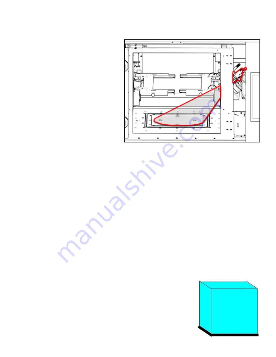
The IR sensor provides feedback of actual part bed
temperature. The blackbody is used to calibrate the
IR sensor during the Offline IR Calibration. See printer
user guide for the Offline IR cal procedure. During
print jobs, automatic Real time calibration checks are
done to check for IR sensor remains in calibration.
•
Part Bed temp too high results in hard part cake/hard break out/growth on parts. In extreme cases, the part cake will melt.
•
Part Bed temp too low could result in curled parts. In extreme cases, parts curl up so much that the roller catches and jams.
•
Why you might need to adjust Part Bed Set Point:
◊
Powder blend (#1 reason to adjust)
°
Default part bed set point in each material should be good for recommended blend ratio for that material
°
If part cake at breakout is too soft overall, then increase the part bed set point next build by small increment (0.5 to
1.0 degrees).
°
If part cake at breakout is too hard overall, then decrease the part bed set point next build by small increment (0.5
to 1.0 degrees).
◊
Blackbody calibration is incorrect or blackbody is damaged.
Potential Print Problems
• Excessive laser energy
will affect material outside the cross-section of the part and cause growth.
•
Insufficient laser energy
does not fuse the part completely, which results in porous, weak parts.
•
If the
print bed temperature is too low
, the parts will curl as the laser scans them.
•
If the
print bed temperature is too high
, the parts will be difficult to remove from the surrounding material.
•
If the
feed material temperature is too low
, the parts will be cooled too quickly when the material is rolled across the bed
and they will curl.
•
If the
feed material temperature is too high
, the material will not be released from the feed hopper and chute correctly,
and the material will not roll correctly in front of the roller.
Before proceeding with troubleshooting, keep in mind the following information:
IR Sensor field of view
BONUS Z
Description:
Bonus Z occurs when the laser melts a part beyond the specified depth—
usually 0.1 mm (0.004 inches) on the first few scans—and causes vertical growth in the Z
axis. The difference between growth and bonus Z is that growth may occur on any part
edge, while bonus Z occurs only on downward facing surfaces.


