21
3D SYSTEMS, INC
.
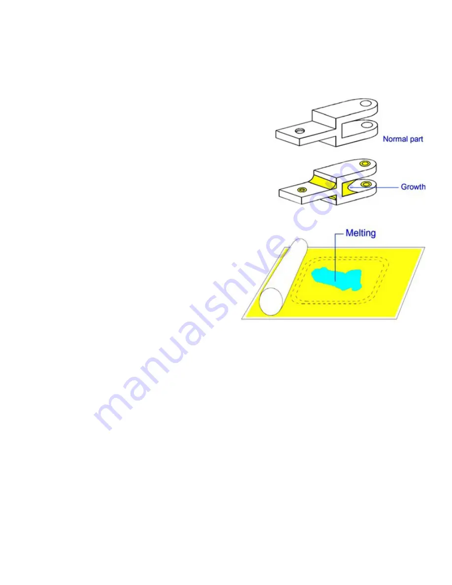
GROWTH
•
In the Warm-up stage of the Print Profile, ramping the heater set points.
•
Use Offline Calibration to make sure IR sensor is calibrated. Refer to the section titled “Offline IR Calibration”.
•
If you have performed all the preceding actions and melting still occurs, you may need to call certified service personnel to
calibrate the IR sensor.
Related Problems:
Crystals and Condensation
,
Melting, Print Bed
,
Cracking of Print Bed
Description:
Growth occurs as material sinters on the part, blurring features
and altering part dimensions. Growth is particularly apparent with small
features or small holes. The difference between growth and Bonus Z is
that growth may occur on any part edge, while Bonus Z occurs only on
downward-facing surfaces.
Theory of Cause:
The laser power may be excessive for thick cross- sections,
or the print bed temperature may be too high.
Visual Signs:
Growth may not be apparent during the print.
Consequences:
If the part has detailed features, the features may blur. Parts
may be oversized. Parts may be difficult or even impossible to break out.
Corrective Action:
Reduce the Part Heater PID Set Point parameter. Reduce
the Fill Laser Power parameter.
Related Problems:
Wash Out
MELTING, PRINT BED
Description:
The material in the print bed melts and solidifies.
Theory of Cause:
Possible causes include:
•
IR sensor not calibrated correctly or dirty.
•
Part Heater Set Point too high.
•
System trying to reach the temperature set point too
quickly.
Visual Signs:
Melting first occurs in small patches in the hottest
areas of the print bed. Observing which areas melt first indicates
the hottest spots in your print bed.
Consequences:
Melting occurs after glazing. The print bed temperature increases. Melting is a far more serious condition than
glazing.
Corrective Action:
Terminate the build. There are several actions you can take to prevent melting:
•
In the Print Parameters Profile, reduce the Part Heater Set Point and/or use ramping for the heater set points.
•
Make sure IR sensor block temperature is correct and that the core heater is working.
•
Perform an Offline IR sensor calibration. Refer to the section titled “Offline IR Calibration.”
•
Refer to the section
Cleaning up the SLS System
.
•
If none of the above actions prevents melting, call certified service personnel
Related Problems:
Cracking of Print Bed
,
Crystals and Condensation
, and
Glazing, During Print
MISSED SCAN
Description:
The laser does not completely scan the fill area in a part.
Theory of Cause:
The STL file is incorrect. This problem is not material related.
Visual Signs:
You can observe that the scanned area is incorrect.
Consequences:
The part geometry is incorrect, and the part may have poor properties.
Corrective Action:
Depending on the severity of the problem, you may need to terminate the print and start over. If the
missed scan occurs only on one layer or slice, you may be able to complete the print.
If you experience missed scans, make it a practice to verify that the STL file is not missing facets and that the normals are
correct prior to beginning a print by using the Preview application. If the STL file is incorrect, you next need to verify that the
original CAD file is correct.
If the original CAD file is correct, the STL file could be corrupt. Generate a new one and preview the print again. If the problem
recurs, contact 3D Systems customer support.


