8
3D SYSTEMS, INC
.
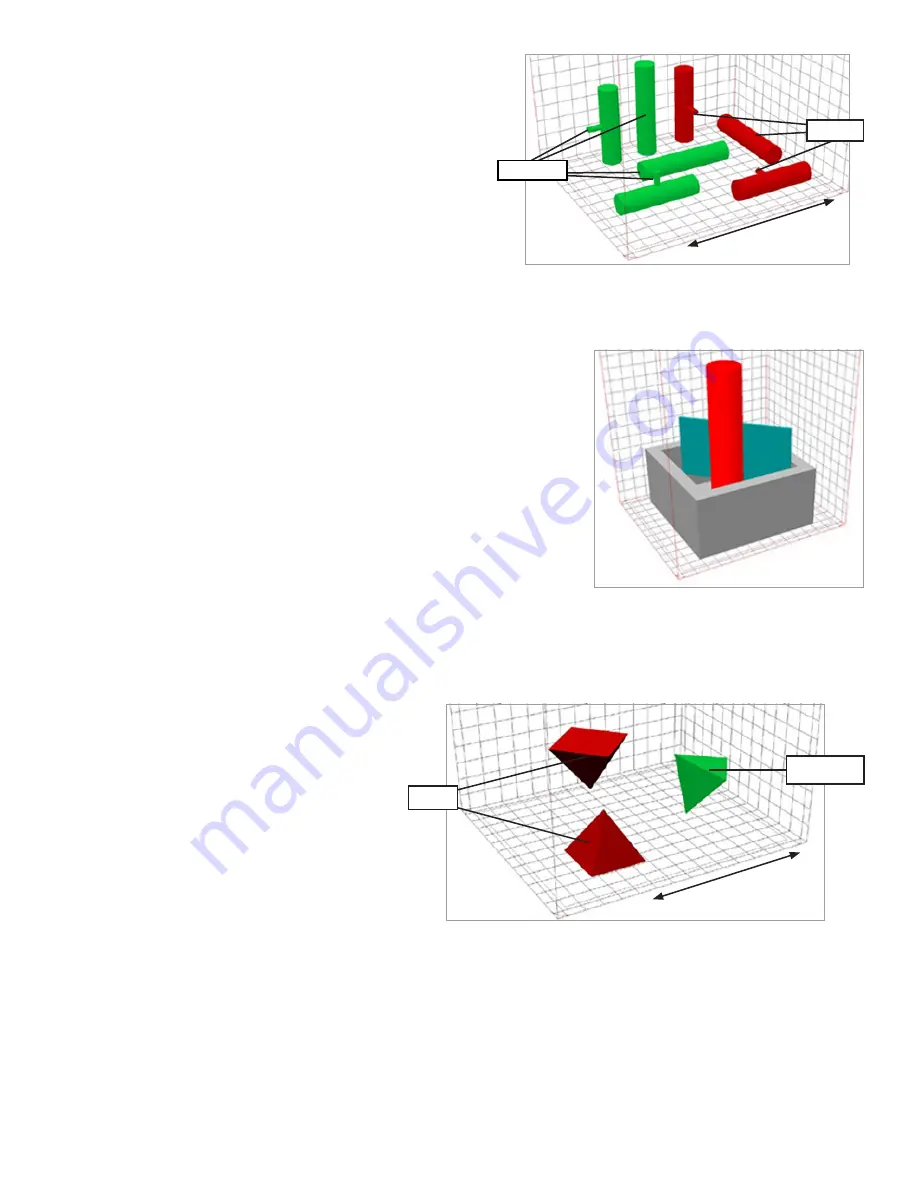
Cylinders and Holes
•
Building a cylinder horizontally is faster; but building it
vertically eliminates Z stepping on the sides of the cylinder.
•
Holes (or inside diameters of hollow cylinders) will also have a
better appearance when built in X/Y plane
•
If the cylinder has another smaller cylinder attached to it, and is
lying down, make sure that the smaller cylinder is facing in an
upward orientation.
•
If standing up, orient the smaller cylinder in the direction of the
roller.
Closed Boxes, Cylinders, and Shapes
Geometries that are closed on all but one side should be placed in the print area with the open side facing up. This reduces heat
buildup in the print cake and the part, making breakout easier and extending material life.
Nesting
You can nest smaller parts within larger ones to utilize more of the print area, as
long as the smaller parts can be removed after printing. If you nest parts, you
should maintain a minimum of 0.25 inches (6.35 mm) between the closest walls
of each part to the others. The part containing the nested parts should always be
facing with the open side up.
Triangular
Try to place the triangular shapes in the print so
that none of the three sides is perpendicular to
the direction of the roller motion, and so that the
base is not at the top in orientation. This offers less
resistance to the material as it flows across the print
bed (thus reducing the possibility of shifting) and will
result in a flatter base.
Large blocky part
Thick cross-sections that have features with X/Y slices or Z depth greater than 12.7 mm (0.5 in.) are more likely to experience
distortion. Start these demanding parts later in the build (at greater Z), after other parts have already been built underneath
Rotating the part a few degrees about X and/or Y can help to mitigate this distortion. Rotation to 30° is shown to give good
results. Along with rotating around X and Y axes, rotating around the Z axis can also help reduce distortion
Refer to the
Distortion
section for more information.
Mating Surfaces
Parts that are to be printed in more than one piece, or parts that will have mating surfaces, should always be placed such that
the mating surfaces are printed in the same orientation. It is preferable that the mating surfaces be printed facing upward for
flatness. If this is not possible, print the mating surfaces in the Z-axis. The least desirable-choice for orientation would be to
print the parts with the mating surfaces facing downward.
Preferred
Avoid
Roller Motion
Avoid
Preferred
Roller Motion
Orientation for cross sections


